Toyota Sienna Service Manual: Registration
1. REGISTRATION TRANSMITTER CODE
HINT: The garage door opener is built in the dome lamp assembly No.1. When transmitter codes for garage door, gate, entry gate, door lock, home lighting system or security system are registered with the garage door opener, be sure to register them again whenever replacing the dome lamp assembly No.1.
(a) After the dome lamp assembly No.1 has been replaced, register transmitter codes with the garage door opener (Registration mode).
NOTICE:
- While the transmitter code for a system (garage, door, gate, etc.) is being registered, the system may operate. During code registration and while the system is in operation, be sure that no people or objects are in the way.
- Be sure to stop the engine and remove the key from the ignition switch before transmitter code registration.
- The garage door opener does not apply to systems manufactured before April 1, 1982 and systems that do not comply with the Federal Safety Standards.
- Garage doors without a jam protection function do not meet the Federal Safety Standards.
HINT:
- Every one of the garage door opener switches can have only one transmitter code; total 3 transmitter codes can be registered with the garage door opener.
- Even if the battery is disconnected, transmitter codes registered with the garage door opener will not be erased.
- Even if you attempt to rewrite the transmitter code registered with the garage door opener and the attempt has failed, the registered transmitter code will not be erased.
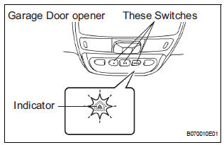
- Select a garage door opener switch for transmitter code registration.
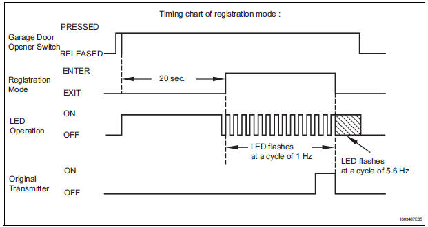
- Press and hold the selected switch for 20 seconds. Then, the garage door opener enters registration mode.
HINT: When the garage door opener is in registration mode, the LED changes from ON to flashing at a cycle of 1 Hz. (In the case of the "rolling code" type, the garage door indicator will flash at a cycle of 8.8 Hz for 1.6 seconds at first and then change the flash cycle to 1 Hz after the garage door opener has entered registration mode.)
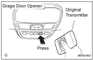
- After the garage door opener has entered registration mode, bring the original transmitter of the system within 1 inch of the garage door opener while pressing the switch of the garage door opener. Under this condition, press the original transmitter.
- When the transmitter code registration has been completed correctly, the indicator of the garage door opener flashes at a cycle of 5.6 Hz. When this happens, release both the switch and the original transmitter.
HINT:
- If the code registration has failed, the battery of the original transmitter may be weak or the system may not meet the garage door opener. In this case, press the original transmitter repeatedly. Some transmitters may need 1 to 2 seconds to stop transmitting signals.
- If the transmitter code registration has not been completed in 90 seconds after the garage door opener has entered registration mode, the garage door opener will enter low power mode (See step c).
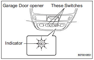
- Erase the transmitter codes (Clear mode).
HINT:
- All the transmitter codes registered in the garage door opener are erased at the same time (maximum 3 codes).
- If the switches are released within 10 seconds after the transmitter codes have been erased, the garage door opener will enter registration mode.
- If the switches are held for 10 seconds or more after the transmitter codes have been erased, default codes will be set to all the 3 switches of the garage door opener. With this default code, you can check operation of the garage door opener using a tester.
- Press and hold the 2 switches at both ends of the garage door opener simultaneously for 20 seconds. Then, the indicator starts flashing at a cycle of 5.6 Hz. Releasing the switches will end clear mode.
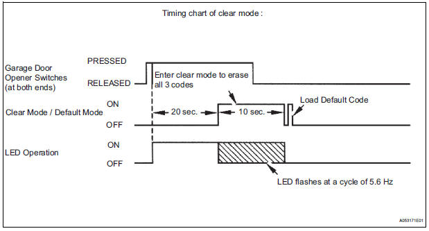
- Low power mode:
- If the switch of the garage door opener is held for 75 seconds or more, the garage door opener will enter low power mode to economize the power consumption. When the garage door opener has entered low power mode, the indicator goes off.
 Garage door opener system
PARTS LOCATION
...
 Inspection
1. INSPECT GARAGE DOOR OPENER
Press the switch and check that each red LED turns
on. If one or more of the switches does not turn on
the LED, confirm normal operation of the fuse and ...
Other materials:
Taillight Relay Circuit
DESCRIPTION
The Multiplex network body ECU controls TAIL relay when signal is received
from headlight dimmer
switch assembly.
WIRING DIAGRAM
INSPECTION PROCEDURE
1 PERFORM ACTIVE TEST BY INTELLIGENT TESTER
Connect the intelligent tester to DLC3.
Turn the ignition switch ON and ...
GCWR, TWR and Unbraked TWR
Confirm that the gross trailer weight, gross combination weight, gross
vehicle weight, gross axle weight and tongue weight are all within the
limits.
GCWR*
2WD models: 8900 lb. (4037 kg)
AWD models: 8990 lb. (4078 kg)
TWR*
3500 lb. (1588 kg)
Unbraked TWR*
1000 lb. (454 kg)
*: These models ...
Disposal
1. DISPOSE OF FRONT SEAT OUTER BELT ASSEMBLY
(WHEN INSTALLED IN VEHICLE)
NOTICE:
Never dispose of a front seat outer belt assembly
with an deactivated pretensioner.
The seat belt pretensioner produces an exploding
sound when it activates, so perform the operation
outdoors w ...
