Toyota Sienna Service Manual: Parts location
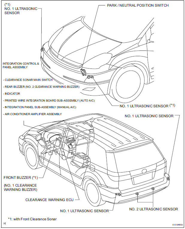
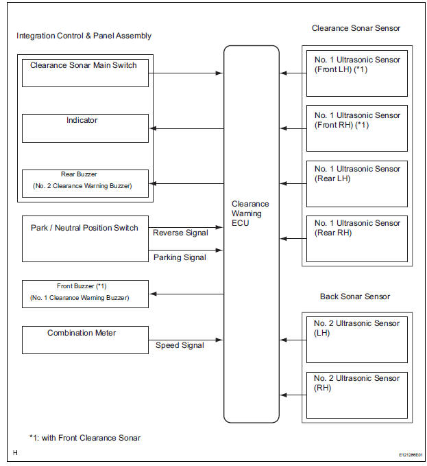
SYSTEM DIAGRAM
 Precaution
1. NOTES FOR CLEARANCE SONAR SYSTEM
Under the following conditions, the sensor of the
clearance sonar may not operate properly:
Foreign matter such as snow or mud gets on the
...
 System description
1. GENERAL
This system uses ultrasonic sensors to detect any
obstacles at the corners and the rear of the vehicle.
The system then informs the driver of the distance
between the sens ...
Other materials:
Disassembly
1. REMOVE REAR SEAT LEG COVER LH
Remove the 2 screws and seat leg cover.
2. REMOVE REAR SEAT LEG COVER RH
Remove the 2 screws and seat leg cover.
3. REMOVE REAR SEAT LEG SIDE COVER LH
Remove the 2 screws and seat leg side cover.
4. REMOVE LH SEAT REAR SEAT LOCK ...
Diagnostic trouble code chart
HINT:
The parameters listed in the chart may not confirm exactly to
those read during the DTC check due to the type of
instrument or other factors.
If a trouble code is displayed during the DTC check in the
check mode, check the circuit for the code listed in the table
below. For details of ...
Diagnosis system
1. CHECK DLC3
The ECU uses ISO 15765-4 for communication.
The terminal arrangement of the DLC3 complies
with SAE J1962 and meets the ISO 15765-4 format.
NOTICE:
*: Before measuring the resistance, leave the
vehicle as is for at least 1 minute and do not
operate the ignition s ...
