Toyota Sienna Service Manual: PBD Pulse Sensor Malfunction
DTC B2222 PBD Pulse Sensor Malfunction
DESCRIPTION
- A pulse sensor is built into the back door for a jam and foreign object detection and for back door position detection. The jam and foreign object detection feature of the pulse sensor monitors the operating speed of the back door while the power back door is in operation. The back door position detection feature of the pulse sensor monitors the back door location. If the back door position detection feature outputs a pulse signal that is out of the normal range, the power back door ECU will set DTC B2222.
- If DTC B2222 sets, the power back door system will be turned off. Thus, the back door can be moved freely and will be switched to manual operation mode (not electrically controlled).
- In order to restore the power back door system to normal operation mode, first solve the problem indicated by DTC B2222 and then manually close the back door fully (reset operation).
|
DTC No. |
DTC Detection Condition |
Trouble Area |
|
B2222 |
Power back door does not operate |
|
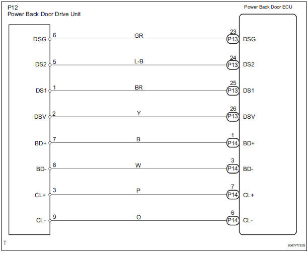
WIRING DIAGRAM
INSPECTION PROCEDURE
1 CHECK WIRE HARNESS (POWER BACK DOOR DRIVE UNIT - POWER BACK DOOR ECU)

- Disconnect the P12 unit and P13 ECU connectors.
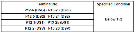
- Check the resistance between the wire harness side connectors.
Resistance (Check for open circuit)
2 INSPECT POWER BACK DOOR DRIVE UNIT
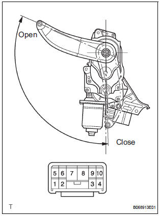
- Remove the unit.
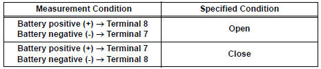
- Connect the battery positive (+) lead to terminal 3 and battery negative (-) terminal lead to terminal 9.
- Apply battery voltage to the terminals and check the motor operation.
OK
- Check the resistance of the clutch terminals.
Resistance
- Reinstall the unit with the connector connected.
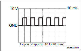
- Check the pulse of the pulse sensor.
- Using an oscilloscope, check the pulse generated when the door is manually opened and closed.
Reference
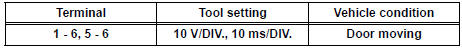
HINT: A cycle of the pulse changes between approx. 10 to 20 msec. according to the speeds that the slide door is moving.
NOTICE: When disconnecting the drive unit, initialize the power back door system
REPLACE POWER BACK DOOR ECU
 Diagnostic trouble code chart
If a malfunction code is displayed during the DTC check,
check the circuit listed for that code in the table below.
(Proceed to the page given for that circuit.)
POWER BACK DOOR SYSTEM
...
 Power Back Door does not Operate
DESCRIPTION
The power back door operates only when the power back door main
switch is ON. The power back
door ECU controls the power back door by activating the back door motor
(built into ...
Other materials:
Air conditioning
SST
RECOMMENDED TOOLS
HINT:
Torx is a registered trademark of Textron Inc.
EQUIPMENT
LUBRICANT
SUPPLEMENTAL RESTRAINT SYSTEM
SST
RECOMMENDED TOOLS
HINT:
Torx is a registered trademark of Textron lnc.
EQUIPMENT
SEAT BELT
SST
RECOMMENDED TOOLS
EQUIPMENT
THEFT ...
How to proceed with
troubleshooting
HINT:
*: Use the intelligent tester.
1 VEHICLE BROUGHT TO WORKSHOP
2 CUSTOMER PROBLEM ANALYSIS
Confirm problem symptoms
3 CHECK MULTIPLEX COMMUNICATION SYSTEM*
Check if the multiplex communication system DTC is
output.
HINT:
The center airbag sensor assembly of this system is
co ...
Removal
HINT:
Use the same procedures for the RH side and LH side.
The procedures listed below are for the LH side.
1. PRECAUTION
CAUTION:
Be sure to read "PRECAUTION" thoroughly before
servicing.
2. DISCONNECT CABLE FROM NEGATIVE BATTERY
TERMINAL
CAUTION:
Wait for 90 s ...
