Toyota Sienna Service Manual: Rear Airbag Sensor RH Circuit Malfunction
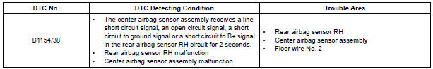
DTC B1154/38 Rear Airbag Sensor RH Circuit Malfunction
DESCRIPTION
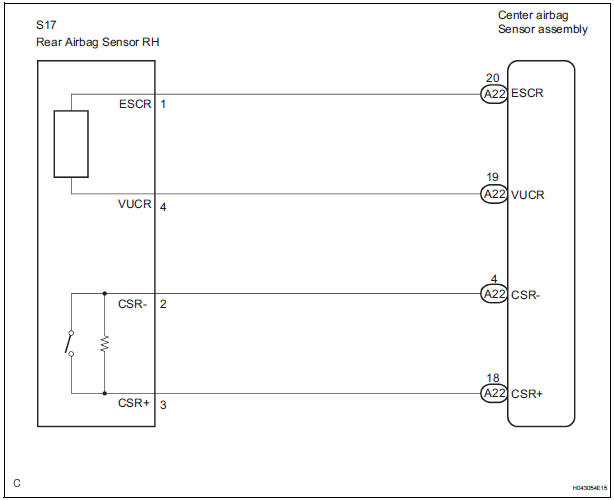
The rear airbag sensor RH circuit consists of the center airbag sensor assembly and rear airbag sensor RH.
If the center airbag sensor assembly receives signals from the rear airbag sensor RH, it judges whether or not the SRS should be activated.
DTC B1154/38 is recorded when a malfunction is detected in the rear airbag sensor RH circuit.
WIRING DIAGRAM
INSPECTION PROCEDURE
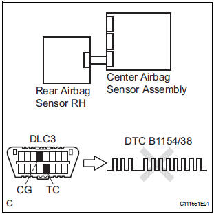
1 CHECK DTC
- Turn the ignition switch to the ON position, and wait for at least 60 seconds.
- Clear the DTCs stored in memory.
- Turn the ignition switch to the LOCK position.
- Turn the ignition switch to the ON position, and wait for at least 60 seconds.
- Check the DTCs.
OK: DTC B1154/38 is not output.
HINT: Codes other than code B1154/38 may be output at this time, but they are not related to this check.
USE SIMULATION METHOD TO CHECK
2 CHECK CONNECTION OF CONNECTORS
- Turn the ignition switch to the LOCK position.
- Disconnect the negative (-) terminal cable from the battery, and wait for at least 90 seconds.
- Check that the connectors are properly connected to the center airbag sensor assembly and the rear airbag sensor RH.
OK: The connectors are connected.
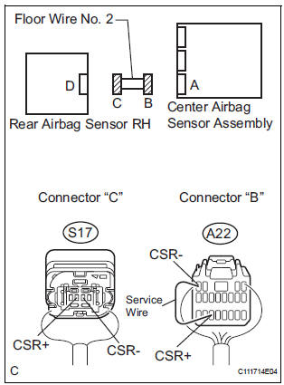
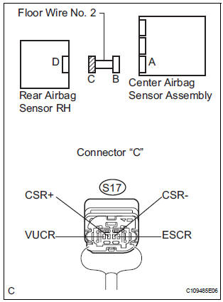
3 CHECK FLOOR WIRE NO. 2 (OPEN)
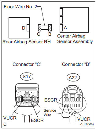
- Disconnect the connectors from the center airbag sensor assembly and the rear airbag sensor RH.
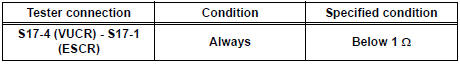
- Using a service wire, connect A22-19 (VUCR) and A22-
20 (ESCR) of connector "B".
NOTICE: Do not forcibly insert a service wire into the terminals of the connector when connecting.
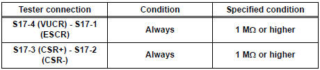
- Measure the resistance according to the value(s) in the table below.
Standard resistance
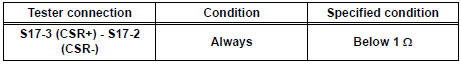
- Using a service wire, connect A22-18 (CSR+) and A22-4
(CSR-) of connector "B".
NOTICE: Do not forcibly insert a service wire into the terminals of the connector when connecting.
- Measure the resistance according to the value(s) in the table below.
Standard resistance
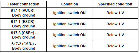
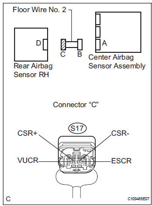
4 CHECK FLOOR WIRE NO. 2 (SHORT TO B+)
- Disconnect the service wire from connector "B".
- Connect the negative (-) terminal cable to the battery, and wait for at least 2 seconds.
- Turn the ignition switch to the ON position.
- Measure the voltage according to the value(s) in the table below.
Standard voltage
5 CHECK FLOOR WIRE NO. 2 (SHORT TO GROUND)
- Turn the ignition switch to the LOCK position.
- Disconnect the negative (-) terminal cable from the battery, and wait for at least 90 seconds.
- Measure the resistance according to the value(s) in the table below.
Standard resistance
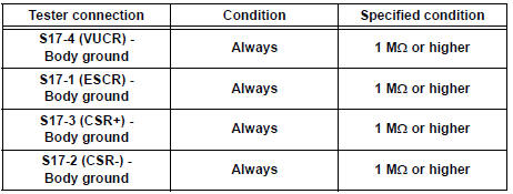
6 CHECK FLOOR WIRE NO. 2 (SHORT)
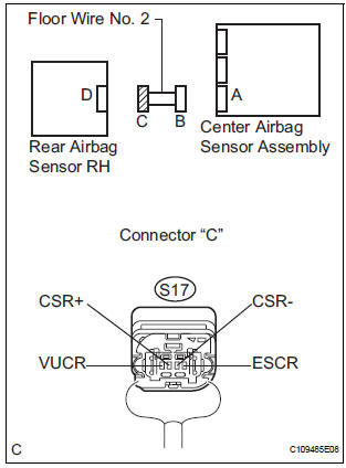
- Measure the resistance according to the value(s) in the table below.
Standard resistance
7 CHECK REAR AIRBAG SENSOR RH
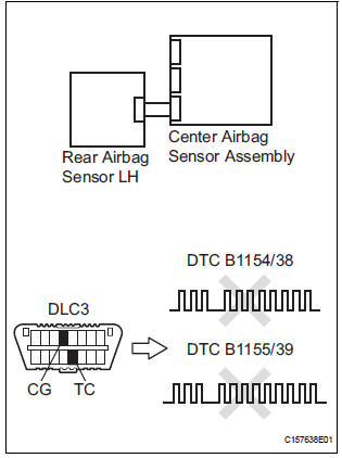
- Connect the connector to the center airbag sensor assembly.
- Interchange the rear airbag sensor LH with RH and connect the connectors to them.
- Connect the negative (-) terminal cable to the battery, and wait for at least 2 seconds.
- Turn the ignition switch to the ON position, and wait for at least 60 seconds.
- Clear the DTCs stored in memory.
- Turn the ignition switch to the LOCK position.
- Turn the ignition switch to the ON position, and wait for at least 60 seconds.
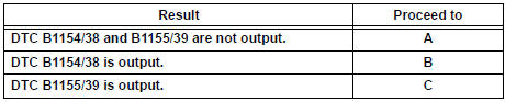
- Check the DTCs.
Result
HINT: Codes other than DTC B1154/38 and B1155/39 may be output at this time, but they are not related to this check.
USE SIMULATION METHOD TO CHECK
 Seat Position Airbag Sensor Circuit Malfunction
DTC B1153/25 Seat Position Airbag Sensor Circuit Malfunction
DESCRIPTION
The seat position airbag sensor circuit consists of the center airbag sensor
assembly and the seat
position airbag sensor. ...
 Rear Airbag Sensor LH Circuit Malfunction
DTC B1155/39 Rear Airbag Sensor LH Circuit Malfunction
DESCRIPTION
The rear airbag sensor LH circuit consists of the center airbag sensor
assembly and rear airbag sensor
LH.
If the center airb ...
Other materials:
No Communication in Immobiliser System
DTC B2796 No Communication in Immobiliser System
DTC B2798 Communication Malfunction No. 2
DESCRIPTION
These codes are stored in the memory when a key that does not have a
transponder chip is inserted or if
communication between the key and transponder key ECU is impossible.
DTC No ...
Rear wheel alignment
ADJUSTMENT
NOTICE:
For vehicles equipped with VSC, if wheel alignment has
been adjusted, and if suspension or underbody
components have been removed/installed or replaced, be
sure to perform the following initialization procedure in
order for the system to function normally:
1. Disconnect the ...
Location of the spare tire, jack and tools
Spare tire
Jack handle
Tire bag
Jack
Wheel nut wrench
Adapter socket
Tire strap
WARNINGUsing the tire jack
Observe the following precautions.
Improper use of the tire jack may cause the vehicle to suddenly fall off
the jack, leading to death or serious injury. ...
