Toyota Sienna Service Manual: Vehicle Speed Signal Circuit between Radio and Navigation Assembly and Combination Meter
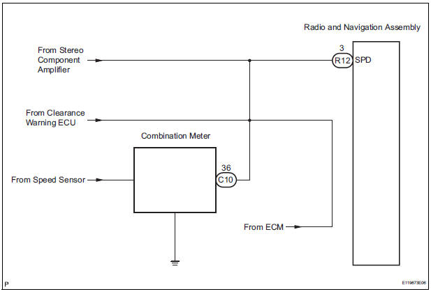
DESCRIPTION The radio and navigation assembly receives a vehicle speed signal from the combination meter and information about the GPS antenna, and then adjusts vehicle position.
HINT:
- A voltage of 12 V or 5 V is output from each ECU and then input to the combination meter. The signal is changed to a pulse signal at the transistor in the combination meter. Each ECU controls the respective system based on the pulse signal.
- If a short occurs in an ECU, all systems in the diagram below will not operate normally.
WIRING DIAGRAM
INSPECTION PROCEDURE
1 CHECK OPERATION OF SPEEDOMETER
- Drive the vehicle and check if the function of the speedometer on the combination meter is normal.
OK: Actual vehicle speed and the speed indicated on the speedometer are the same
HINT: The vehicle speed sensor is functioning normally when the indication on the speedometer is normal.
2 INSPECT RADIO AND NAVIGATION ASSEMBLY
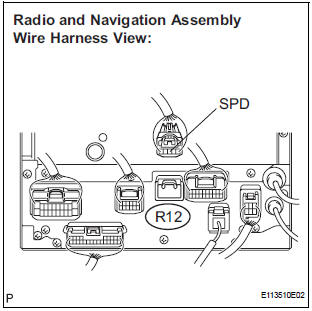
- Disconnect the radio and navigation assembly connector R12.
- Measure the voltage.
- Jack up either one of the drive wheels.
- Move the shift lever to the neutral position.
- Turn the ignition switch to the ON position
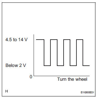
- Measure the voltage between terminal SPD of the radio and navigation assembly and body ground when the drive wheels are turned slowly.
OK: Voltage pulses as shown in the illustration.
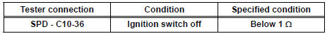
3 CHECK HARNESS AND CONNECTOR (COMBINATION METER - RADIO AND NAVIGATION ASSEMBLY)
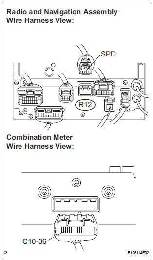
- Disconnect the radio and navigation assembly connector R12 and combination meter connector C10.
- Measure the resistance according to the value(s) in the table below.
Standard resistance
4 CHECK HARNESS AND CONNECTOR (COMBINATION METER - RADIO AND NAVIGATION ASSEMBLY)
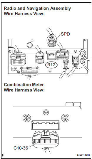
- Disconnect the radio and navigation assembly connector R12 and combination meter connector C10.
- Measure the resistance according to the value(s) in the table below.
Standard resistance
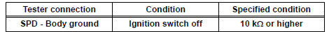
HINT: If the resistance between terminal SPD and body ground is less than 10 kΩ, there may be a short in a wire harness, connector, or an ECU.
REPLACE COMBINATION METER
 Black Screen
INSPECTION PROCEDURE
1 CHECK DISPLAY SETTING
Check that the display is not in "Screen OFF" mode.
OK:
The display setting is not in "Screen OFF" mode.
2 CHECK IMAGE QUALIT ...
 Steering Pad Switch Circuit
DESCRIPTION
This circuit sends an operation signal from the steering pad switch to the
radio receiver.
If there is an open in the circuit, the navigation system cannot be operated
using the st ...
Other materials:
Air conditioning
SST
RECOMMENDED TOOLS
HINT:
Torx is a registered trademark of Textron Inc.
EQUIPMENT
LUBRICANT
SUPPLEMENTAL RESTRAINT SYSTEM
SST
RECOMMENDED TOOLS
HINT:
Torx is a registered trademark of Textron lnc.
EQUIPMENT
SEAT BELT
SST
RECOMMENDED TOOLS
EQUIPMENT
THEFT ...
Rear view monitor system precautions
Area displayed on screen
The rear view monitor system
displays an image of the view
from the bumper of the rear
area of the vehicle.
The image on the rear view monitor system can be adjusted.
The area displayed on the
screen may vary according to
vehicle orientation conditions.
...
Camshaft Position Sensor "A" Circuit
DESCRIPTION
The intake camshaft's Variable Valve Timing (VVT) sensor (G signal) consists
of a magnet and MRE
(Magneto Resistance Element).
The VVT camshaft drive gear has a sensor plate with 3 teeth on its outer
circumference. When the gear
rotates, changes occur in the air gaps betwee ...
