Toyota Sienna Service Manual: Rear Airbag Sensor LH Circuit Malfunction
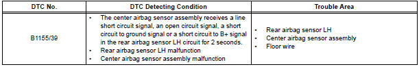
DTC B1155/39 Rear Airbag Sensor LH Circuit Malfunction
DESCRIPTION
The rear airbag sensor LH circuit consists of the center airbag sensor assembly and rear airbag sensor LH.
If the center airbag sensor assembly receives signals from the rear airbag sensor LH, it judges whether or not the SRS should be activated.
DTC B1155/39 is recorded when a malfunction is detected in the rear airbag sensor LH circuit.
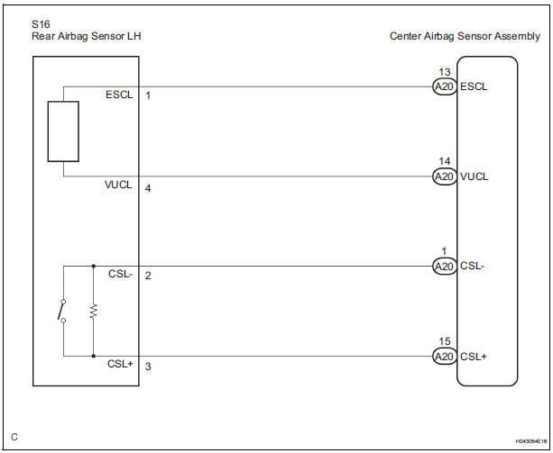
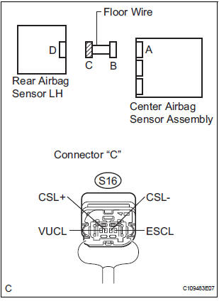
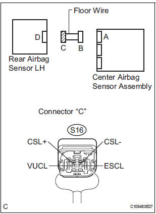
WIRING DIAGRAM
INSPECTION PROCEDURE
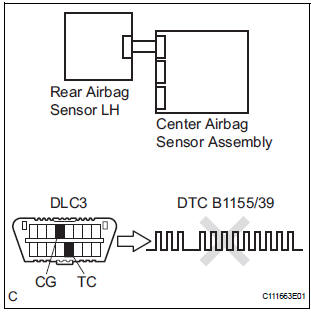
1 CHECK DTC
- Turn the ignition switch to the ON position, and wait for at least 60 seconds.
- Clear the DTCs stored in memory.
- Turn the ignition switch to the LOCK position.
- Turn the ignition switch to the ON position, and wait for at least 60 seconds.
- Check the DTCs.
OK: DTC B1155/39 is not output.
HINT: Codes other than code B1155/39 may be output at this time, but they are not related to this check.
USE SIMULATION METHOD TO CHECK
2 CHECK CONNECTION OF CONNECTORS
- Turn the ignition switch to the LOCK position.
- Disconnect the negative (-) terminal cable from the battery, and wait for at least 90 seconds.
- Check that the connectors are properly connected to the center airbag sensor assembly and the rear airbag sensor LH.
OK: The connectors are connected.
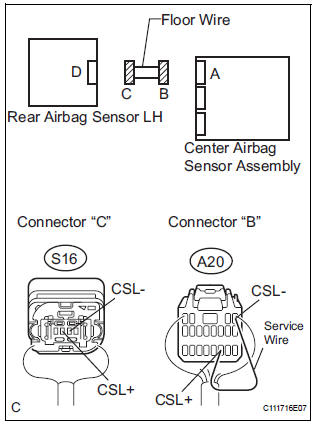
3 CHECK FLOOR WIRE (OPEN)
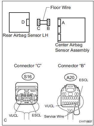
- Disconnect the connectors from the center airbag sensor assembly and the rear airbag sensor LH.
- Using a service wire, connect A20-14 (VUCL) and A20-
13 (ESCL) of connector "B".
NOTICE: Do not forcibly insert a service wire into the terminals of the connector when connecting.
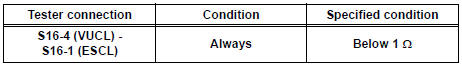
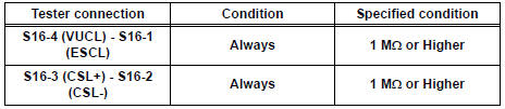
- Measure the resistance according to the value(s) in the table below.
Standard resistance
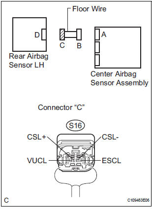
- Using a service wire, connect A20-15 (CSL+) and A20-1
(CSL-) of connector "B".
NOTICE: Do not forcibly insert a service wire into the terminals of the connector when connecting.
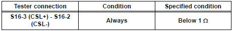
- Measure the resistance according to the value(s) in the table below.
Standard resistance
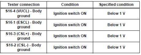
4 CHECK FLOOR WIRE (SHORT TO B+)
- Disconnect SST from connector "B".
- Connect the negative (-) terminal cable to the battery, and wait for at least 2 seconds.
- Turn the ignition switch to the ON position.
- Measure the voltage according to the value(s) in the table below.
Standard voltage
5 CHECK FLOOR WIRE (SHORT TO GROUND)
- Turn the ignition switch to the LOCK position.
- Disconnect the negative (-) terminal cable from the battery, and wait for at least 90 seconds.
- Measure the resistance according to the value(s) in the table below.
Standard resistance
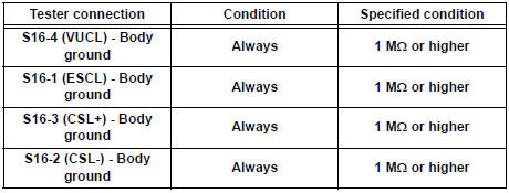
6 CHECK FLOOR WIRE (SHORT)
- Measure the resistance according to the value(s) in the table below.
Standard resistance
7 CHECK REAR AIRBAG SENSOR LH
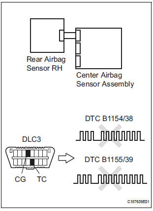
- Connect the connector to the center airbag sensor assembly.
- Interchange the rear airbag sensor RH with LH and connect the connectors to them.
- Connect the negative (-) terminal cable to the battery, and wait for at least 2 seconds.
- Turn the ignition switch to the ON position, and wait for at least 60 seconds.
- Clear the DTCs stored in memory.
- Turn the ignition switch to the LOCK position.
- Turn the ignition switch to the ON position, and wait for at least 60 seconds.
- Check the DTCs.
Result
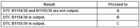
HINT: Codes other than DTC B1154/38 and B1155/39 may be output at this time, but they are not related to this check.
USE SIMULATION METHOD TO CHECK
 Rear Airbag Sensor RH Circuit Malfunction
DTC B1154/38 Rear Airbag Sensor RH Circuit Malfunction
DESCRIPTION
The rear airbag sensor RH circuit consists of the center airbag sensor
assembly and rear airbag sensor
RH.
If the center airb ...
 Short in Curtain Shield Squib RH Circuit
DTC B1160/83 Short in Curtain Shield Squib RH Circuit
DESCRIPTION
The curtain shield squib RH circuit consists of the center airbag sensor
assembly and the curtain shield
airbag assembly RH.
T ...
Other materials:
Installing the second seats
Installing the second outside seats
Align the marking on the seat side cover to the marking on the
rail cover and align the marking on the seat front/back cover to
the rail.
Tip-up seat
Ottoman seat
Lower the seat and engage the latches.
If you locked the seat lat ...
Air-fuel ratio (a/f) and heated oxygen (ho2)
sensor heater monitors (front a/f and rear ho2 sensor
type)
(a) Preconditions
The monitor will not run unless:
The MIL is OFF.
(b) Drive Pattern
(1) Connect an intelligent tester to the DLC3.
(2) Turn the ignition switch to the ON position.
(3) Clear the DTCs.
(4) Start the engine.
(5) Allow the engine to idle for 10 minutes or more.
...
Power Slide Door LH does not Operate When Satellite Switch is
Pressed
DESCRIPTION
The power slide door operates only when the power slide door main
switch is ON (switch free: orange
paint on the top of the switch appears). The power slide door ECU LH
controls the power slide door LH,
which activates the slide door motor to open / close the slide do ...
