Toyota Sienna Service Manual: Installation
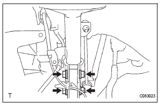
1. INSTALL FRONT AXLE ASSEMBLY LH

(a) Install the 2 bolts, nuts and front axle assembly LH with the 2 bolts and nuts to the shock absorber assembly front LH.
Torque: 230 N*m (2,350 kgf*cm, 170 ft.*lbf)
NOTICE:
- Only when reusing the bolts and nuts, apply the small amount of engine oil to the screw part of the nuts.
- Do not excessively push out the front axle assembly LH.
- Be careful not to damage the outboard joint boot.
- Be careful not to damage the speed sensor rotor.
2. INSTALL FRONT SUSPENSION ARM SUBASSEMBLY LOWER NO.1 LH (See page DS-18)
3. INSTALL TIE ROD END SUB-ASSEMBLY LH (See page DS-18)
4. INSTALL FRONT DISC
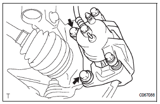
5. INSTALL FRONT DISC BRAKE CALIPER ASSEMBLY LH

(a) Install the front disc brake caliper assembly LH with the 2 bolts to the steering knuckle LH.
Torque: 104 N*m (1,060 kgf*cm, 77 ft.*lbf)
6. INSTALL FRONT AXLE HUB LH NUT
(a) Using a socket wrench (30mm), install a new axle hub LH nut.
Torque: 294 N*m (3,000 kgf*cm, 217 ft.*lbf)
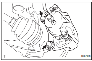
7. SEPARATE FRONT DISC BRAKE CALIPER ASSEMBLY LH
(a) Remove the 2 bolts and separate the front disc brake caliper assembly LH from the steering knuckle LH.
NOTICE: Use a string or other device to keep the brake caliper from hanging down.
8. REMOVE FRONT DISC
9. INSPECT BEARING BACKLASH (See page AH-5)
10. INSPECT AXLE HUB DEVIATION (See page AH-5)
11. INSTALL FRONT DISC
12. INSTALL FRONT DISC BRAKE CALIPER ASSEMBLY LH

(a) Install the front disc brake caliper assembly LH with the 2 bolts to the steering knuckle LH.
Torque: 104 N*m (1,060 kgf*cm, 77 ft.*lbf)
13. INSTALL SPEED SENSOR FRONT LH (See page DS- 18)
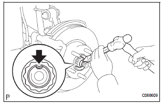
14. INSTALL FRONT AXLE HUB LH NUT

(a) Using a socket wrench (30 mm), install a new axle hub LH nut.
Torque: 294 N*m (3,000 kgf*cm, 217 ft.*lbf) (b) Using a chisel and hammer, stake the axle hub LH nut.
15. INSTALL FRONT WHEEL Torque: 103 N*m (1,050 kgf*cm, 76 ft.*lbf)
16. INSPECT FRONT WHEEL ALIGNMENT
(a) Inspect front wheel alignment (See page SP-4).
17. CHECK ABS SPEED SENSOR SIGNAL
(a) ABS WITH EBD SYSTEM (See page BC-3).
(b) ABS WITH EBD & BA & TRAC & VSC SYSTEM (See page BC-72).
 Reassembly
1. INSTALL FRONT AXLE HUB LH BEARING
(a) Using SST(s) and a press, install a new front axle
hub LH bearing to the steering knuckle LH.
SST 09950-60020 (09951-00810), 09950-70010
(09951-07100 ...
 Rear axle hub bolt
COMPONENTS
Replacement
HINT:
Replace the RH side using the same procedures as for the
LH side.
1. REMOVE REAR WHEEL
2. SEPARATE REAR DISC BRAKE CALIPER
ASSEMBLY LH
(a) Separate rear di ...
Other materials:
Removal
1. PRECAUTION
CAUTION:
Be sure to read "PRECAUTION" thoroughly before servicing.
2. DISCONNECT CABLE FROM NEGATIVE BATTERY
TERMINAL
CAUTION:
Wait for 90 seconds after disconnecting the cable to
prevent the airbag working.
3. REMOVE FRONT SEAT ASSEMBLY (for Manual Seat)
4. REMOVE F ...
Opening the back door from outside the vehicle
Back door opener
Raise the back door while
pressing the back door opener
to release the lock to open the
back door.
Wireless remote control (vehicles with power back door)
Press and hold the switch to open/close the power back door
Vehicles without a smart key
system
Vehicl ...
Removal
1. Remove windshield wiper motor assembly
hint:
(see page ww-4)
2. Remove front outer cowl top panel subassembly
(see page em-27)
3. Drain engine coolant (see page co-6)
4. Remove v-bank cover sub-assembly (see
page em-28)
5. Remove no. 2 Air cleaner inlet (see page em-
28)
6. Remove no. 1 ...
