Toyota Sienna Service Manual: Sound Signal Circuit between Radio Receiver and Television Display Assembly
DESCRIPTION
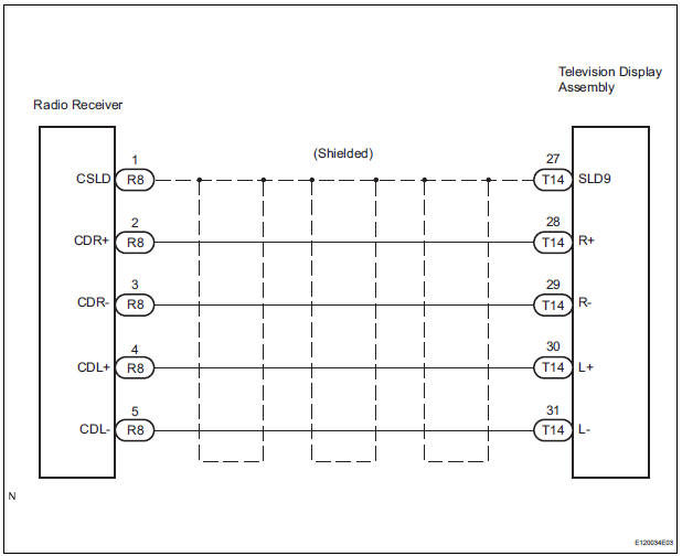
The television display assembly sends a sound signal to the radio receiver through this circuit.
The sound signal that has been sent is amplified by the stereo component amplifier or radio receiver (built-in amplifier), and then is sent to the speakers.
If there is an open or short in the circuit, sound cannot be heard from the speakers even if there is no malfunction in the stereo component amplifier, radio receiver, or speakers.
WIRING DIAGRAM
INSPECTION PROCEDURE
1 CHECK HARNESS AND CONNECTOR (RADIO RECEIVER - TELEVISION DISPLAY ASSEMBLY)
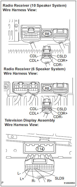
- Disconnect the connectors from the television display assembly and radio receiver.
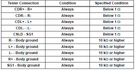
- Measure the resistance according to the value(s) in the table below.
Standard resistance
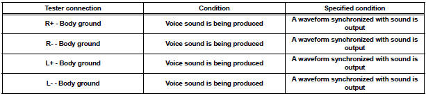
2 INSPECT TELEVISION DISPLAY ASSEMBLY
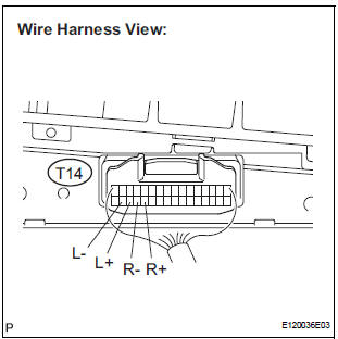
- Reconnect the television display assembly connector.
- Check the waveform according to the conditions shown in the table below
Standard
PROCEED TO NEXT CIRCUIT INSPECTION SHOWN IN PROBLEM SYMPTOMS TABLE
 Sound Signal Circuit between Radio Receiver and Stereo Component
Amplifier
Sound Signal Circuit between Radio Receiver and Stereo Component
Amplifier
DESCRIPTION
The radio receiver sends a sound signal to the stereo component amplifier
through this circuit.
The sound signal that has been sent is amplified by the stereo component
amplifier, ...
 Sound Signal Circuit between Radio Receiver and Stereo Jack Adapter
DESCRIPTION
The stereo jack adapter sends an external device sound signal to the radio
receiver through this circuit.
The sound signal that has been sent is amplified by the stereo component
a ...
Other materials:
Precaution
1. Check that the battery cables are connected to the
correct terminals.
2. Disconnect the battery cables when the battery is
given a quick charge.
3. Do not perform tests with a high voltage insulation
resistance tester.
4. Never disconnect the battery cables while the engine
is runnin ...
System description
1. CRUISE CONTROL SYSTEM
This system is controlled by the ECM, and is activated by
the throttle position sensor and motor. The ECM controls
the following functions: ON-OFF, - (COAST)/SET, +
(ACCEL)/RES (RESUME), CANCEL, vehicle speed
operation, motor output control, and overdrive control.
& ...
Throttle / Pedal Position Sensor / Switch "D"
Circuit Range / Performance
DTC P2121 Throttle / Pedal Position Sensor / Switch "D"
Circuit Range / Performance
HINT:
This DTC relates to the Accelerator Pedal Position (APP) sensor.
DESCRIPTION
Refer to DTC P2120
MONITOR DESCRIPTION
The accelerator pedal position sensor is mounted on the accelerator pedal ...
