Toyota Sienna Service Manual: Reassembly
1. INSTALL BRAKE MASTER LESS RESERVOIR TANK CYLINDER SUB-ASSEMBLY
(a) Apply lithium soap base glycol grease to the 2 brake master cylinder union grommets and install them to the brake master less reservoir tank cylinder subassembly.
(b) Using a pin punch (φ 5 mm) and hammer, install the master cylinder union with the pin.
(c) Install the 2 new O-rings.
(d) Install the brake master less reservoir tank cylinder sub-assembly with the 2 nuts and, 2 bolts.
Torque: 25 N*m (255 kgf*cm, 18 ft.*lbf)
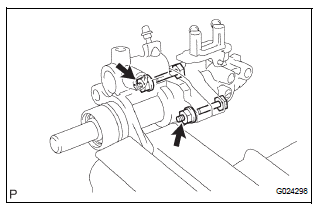
NOTICE: When the diameter converting unit and master cylinder are connected, install the No. 3 piston with no looseness.
(e) Using SST, install the brake tube to the brake master cylinder.
SST 09023-00101 Torque: 15 N*m (155 kgf*cm, 11 ft.*lbf)
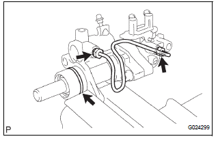
(f) Install the new O-ring.
 Disassembly
1. REMOVE BRAKE MASTER LESS RESERVOIR TANK CYLINDER SUB-ASSEMBLY
(a) Using soft jaws on the vise, hold the brake master
cylinder in a vise through aluminum plates.
(b) Using a screwdriver, re ...
 Installation
1. INSTALL BRAKE MASTER CYLINDER
(a) Install the brake master cylinder with the 2 nuts.
Torque: 13 N*m (130 kgf*cm, 9 ft.*lbf)
(b) Slide the clip and connect the brake master cylinder
reserv ...
Other materials:
Data list / active test
1. READ DATA LIST
HINT:
Using the DATA LIST displayed on the intelligent tester,
you can read the value of the switch, sensor, actuator,
etc. without parts removal. Reading the DATA LIST as
the first step in troubleshooting is one way to shorten the
labor time.
Connect the intelligen ...
Inspection
1. INSPECT SHOCK ABSORBER ASSEMBLY REAR LH
(a) Push down and pull up the shock absorber rod, and
check that there is no unusual resistance or unusual
operation sound.
If there is any malfunction, replace the shock
absorber with a new one.
NOTICE:
When disposing of the shock absorber, se ...
Reassembly
1. INSTALL REAR DOOR WIRE SUB-ASSEMBLY LH
Install the wire.
NOTICE:
When installing the wire, push the areas where
the clips are installed in order to prevent
damage and deformation.
Install the 2 screws.
2. INSTALL REAR DOOR LOCK ASSEMBLY LH
Apply MP grease to the slidi ...
