Toyota Sienna Service Manual: Reassembly
1. INSTALL LOWER RADIATOR GRILLE
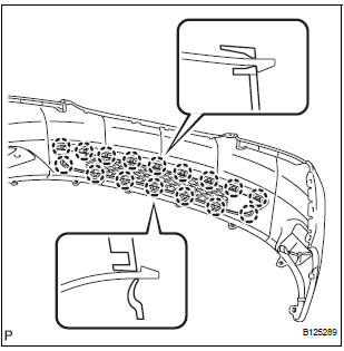
- Engage the 16 claws to install the lower radiator grille to the front bumper cover.
2. INSTALL FRONT BUMPER HOLE COVER LH (w/o Fog Light)

- Engage the 2 pins to install the front bumper hole cover LH to the front bumper cover.
3. INSTALL FRONT BUMPER HOLE COVER RH (w/o Fog Light)
HINT: Perform the same procedure as for the LH side.
4. INSTALL FOG LIGHT ASSEMBLY LH (w/ Fog Light) (See page LI-85)
5. INSTALL FOG LIGHT ASSEMBLY RH (w/ Fog Light)
HINT: Perform the same procedure as for the LH side.
6. INSTALL FRONT BUMPER EMBLEM
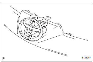
- Engage the 3 claws to install the front bumper emblem to the upper radiator grille.
7. INSTALL UPPER RADIATOR GRILLE
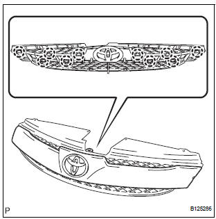
- Engage the 10 claws to install the upper radiator grille to the radiator grille.
8. INSTALL RADIATOR GRILLE

- Engage the 4 claws to install the radiator grille to the front bumper cover.
- Install the 2 bolts and the 2 screws.
Torque: Bolt 5.4 N*m (54 kgf*cm, 48 in.*lbf) Screw 5.0 N*m (51 kgf*cm, 44.3 in.*lbf)
9. INSTALL NO. 1 ULTRASONIC SENSOR (LH side) (w/ Clearance Sonar System) (See page PM-20)
10. INSTALL NO. 1 ULTRASONIC SENSOR (RH side) (w/ Clearance Sonar System)
HINT: Perform the same procedure as for the LH side.
11. INSTALL NO. 1 ULTRASONIC SENSOR RETAINER
12. INSTALL FRONT BUMPER SIDE SUPPORT LH
- Engage the 2 clips to install the front bumper side support LH.
- Install the screw.
Torque: 7.0 N*m (71 kgf*cm, 62.0 in.*lbf)
13. INSTALL FRONT BUMPER SIDE SUPPORT RH
HINT: Perform the same procedure as for the LH side.
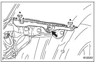
14. INSTALL FRONT BUMPER REINFORCEMENT SUBASSEMBLY
- Install the front bumper reinforcement sub-assembly
with the 6 bolts.
Torque: 50 N*m (510 kgf*cm, 37 ft.*lbf)
15. INSTALL FRONT BUMPER ENERGY ABSORBER
 Disassembly
1. REMOVE FRONT BUMPER ENERGY ABSORBER
2. REMOVE FRONT BUMPER REINFORCEMENT SUBASSEMBLY
Remove the 6 bolts and the front bumper
reinforcement sub-assembly.
3. REMOVE FRONT BUMPER SIDE SU ...
 Installation
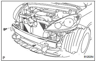
1. INSTALL FRONT BUMPER ASSEMBLY
Push the front bumper onto the front of the vehicle
and engage the claws on the left and right sides of
the front bumper to install it as shown in the
il ...
Other materials:
Installation
1. Install generator assembly
(a) Install the bracket with the bolt.
Torque: 20 N*m (204 kgf*cm, 15 ft.*lbf)
(b) Install the wire harness clamp stay.
Torque: 8.4 N*m (86 kgf*cm, 74 in.*lbf)
(c) Connect the wire harness clamp.
(d) Install the generator assembly to the cylinder ...
Occupant Classification ECU Malfunction
DTC B1795 Occupant Classification ECU Malfunction
DESCRIPTION
DTC B1795 is recorded when a malfunction is detected in the occupant
classification ECU.
Troubleshoot DTC B1771 first when the DTCs B1771 and B1795 are output
simultaneously.
DTC No.
DTC Detecting Condition
...
Reassembly
1. APPLY HIGH TEMPERATURE GREASE
(a) Apply the high temperature grease to the surface on
which the shoe and backing plate attach.
2. INSTALL PARKING BRAKE SHOE LEVER LH
(a) Install the shoe lever and shim to the rear shoe with
a new C-washer.
(b) Using a feeler gauge, measure the clearance.
...
