Toyota Sienna Service Manual: Disassembly
1. REMOVE FRONT BUMPER ENERGY ABSORBER
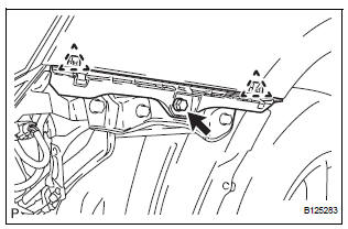
2. REMOVE FRONT BUMPER REINFORCEMENT SUBASSEMBLY
- Remove the 6 bolts and the front bumper reinforcement sub-assembly.
3. REMOVE FRONT BUMPER SIDE SUPPORT LH
- Remove the screw.
- Disengage the 2 clips and remove the front bumper side support LH.
4. REMOVE FRONT BUMPER SIDE SUPPORT RH
HINT: Perform the same procedure as for the LH side.
5. REMOVE NO. 1 ULTRASONIC SENSOR RETAINER (See page PM-19)
6. REMOVE NO. 1 ULTRASONIC SENSOR (LH side) (w/ Clearance Sonar System) (See page PM-19)
7. REMOVE NO. 1 ULTRASONIC SENSOR (RH side) (w/ Clearance Sonar System)
HINT: Perform the same procedure as for the LH side.
8. REMOVE RADIATOR GRILLE
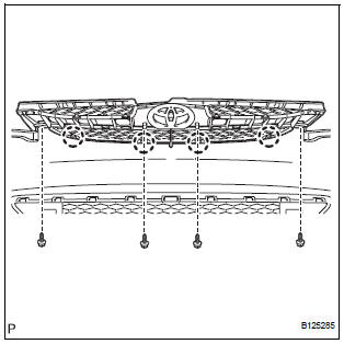
- Remove the 2 bolts and the 2 screws.
- Disengage the 4 claws and remove the radiator grille from the front bumper cover.
9. REMOVE UPPER RADIATOR GRILLE
- Disengage the 10 claws and remove the upper radiator grille from the radiator grille.
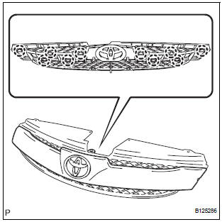
10. REMOVE FRONT BUMPER EMBLEM
- Disengage the 3 claws and remove the front bumper emblem from the upper radiator grille.
11. REMOVE FRONT BUMPER HOLE COVER LH (w/o Fog Light)
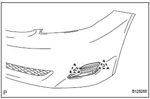
- Disengage the 2 pins and remove the front bumper hole cover LH from the front bumper cover.
12. REMOVE FRONT BUMPER HOLE COVER RH (w/o Fog Light)
HINT: Perform the same procedure as for the LH side.
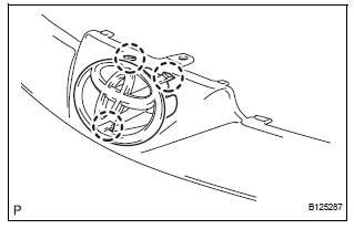
13. REMOVE FOG LIGHT ASSEMBLY LH (w/ Fog Light) (See page LI-82)
14. REMOVE FOG LIGHT ASSEMBLY RH (w/ Fog Light)
HINT: Perform the same procedure as for the LH side.
15. REMOVE LOWER RADIATOR GRILLE
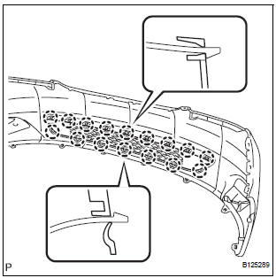
- Disengage the 16 claws and remove the lower radiator grille from the front bumper cover.
 Removal
1. DISCONNECT CABLE FROM NEGATIVE BATTERY
TERMINAL
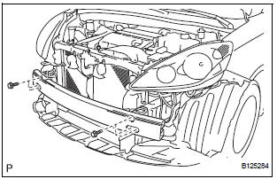
2. REMOVE FRONT BUMPER ASSEMBLY
Remove the 4 screws and separate the fender liner
from the front bumper assembly.
Remove the 8 ...
 Reassembly
1. INSTALL LOWER RADIATOR GRILLE
Engage the 16 claws to install the lower radiator
grille to the front bumper cover.
2. INSTALL FRONT BUMPER HOLE COVER LH (w/o
Fog Light)
Engage ...
Other materials:
Open in ABS Solenoid Relay Circuit
DESCRIPTION
This relay supplies power to each ABS solenoid.
Immediately after the ignition switch is turned to the ON position, the relay
turns on if the solenoid is
determined to be normal as a result of self-diagnosis during initial check.
The relay turns off if an open/short is dete ...
Inspection
1. INSPECT CHARCOAL CANISTER ASSEMBLY
(a) Visually check the charcoal canister for cracks or
damage.
If cracks or damage are found, replace the charcoal
canister assembly.
(b) Check charcoal canister operation.
(1) With the purge port closed, blow 1.67 kPa (17.0
gf/cm2, 0.24 psi) ...
Evaporative Emission Control System Leak Detected
DTC SUMMARY
DESCRIPTION
The circuit description can be found in the EVAP (Evaporative Emission)
System (See page ES-409).
INSPECTION PROCEDURE
Refer to the EVAP System (See page ES-412).
MONITOR DESCRIPTION
5 hours*1 after the ignition switch is turned off, the electric vacuum pump
c ...
