Toyota Sienna Service Manual: Reassembly
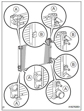
1. Install lower radiator tank
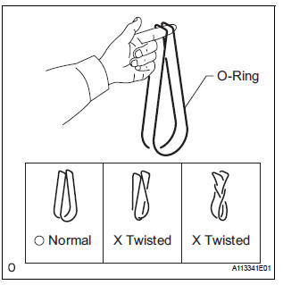
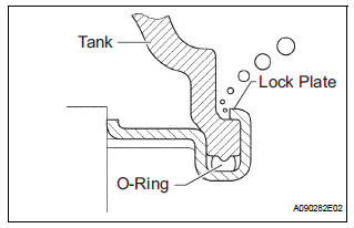
(a) After checking that there are no foreign objects in the lock plate groove, install a new O-ring without twisting it.
HINT: When cleaning the lock plate groove, lightly rub it with sandpaper without scratching it.
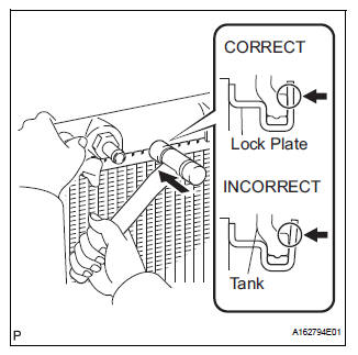
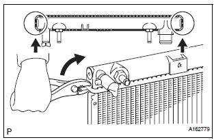
(b) Tap the lock plate with a plastic-faced hammer so that there is no gap between the lock plate and the tank.
| NOTICE: Do not tap the areas protruding around the pipes, brackets or tank ribs. |
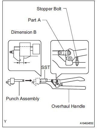
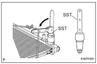
(c) Install the punch assembly to the overhaul handle, inserting it in the hole in part A as shown in the illustration.
SST 09230-01010 (09231-01010, 09231-01020), 09231-14010
(d) While gripping the handle, adjust the stopper bolt so that dimension B is as specified below.
Dimension B: 8.8 mm (0.347 in.)
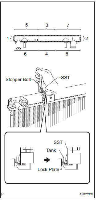
(e) Lightly press SST against the lock plate in the order shown in the illustration. After repeating this procedure a few times, fully crimp the lock plate by squeezing the handle until stopped by the stopper bolt.
SST 09230-01010 (09231-01010, 09231-01020), 09231-14010
NOTICE:
|
(f) Check the lock plate height A after completing the crimping.
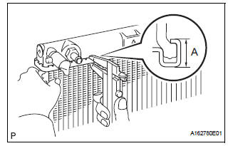
Standard plate height A: 8.8 mm (0.347 in.)
If the height is not as specified, readjust the stopper bolt of the handle and crimp the lock plate again.
2. INSTALL UPPER RADIATOR TANK
HINT: The installation procedure for the upper radiator tank is the same as that for the lower radiator tank.
3. INSTALL DRAIN PLUG
(a) Install a new O-ring to the drain plug.
(b) Install a new O-ring to the air drain plug.
(c) Install the drain plug and air drain plug.
4. INSPECT FOR WATER LEAK
(a) Plug the inlet and outlet pipes of the radiator with SST.
SST 09230-01010 (09231-00030, 09231-00060) (b) Using a radiator cap tester, apply pressure to the radiator.
Standard test pressure: 177 kPa (1.8 kgf/cm2, 26 psi) (c) Submerge the radiator in water.
(d) Inspect for leak.
HINT: On radiators with resin tanks, there is clearance between the tank and lock plate where a minute amount of air will remain, giving the appearance of an air leak when the radiator is submerged in water.
Therefore, before doing the water leak test, first swish the radiator around in the water until all air bubbles disappear.
5. INSTALL RADIATOR WATER INLET
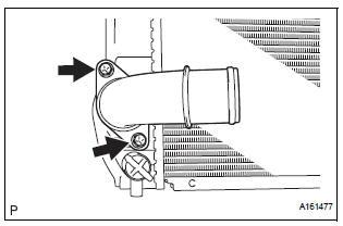
(a) Install the radiator water inlet with the 2 bolts.
Torque: 7.1 N*m (72 kgf*cm, 63 in.*lbf)
 Inspection
1. INSPECT LOCK PLATE FOR DAMAGE
(a) Inspect the lock plate for damage.
HINT:
Reassembly of a deformed tank will be
impossible. Therefore, first correct the shape of
the lock plate groov ...
 Installation
1. Connect inlet sub-assembly
(a) Connect the inlet hose to the radiator.
(b) Install the inlet sub-assembly to the radiator with the
bolt.
Torque: 7.1 N*m (72 kgf*cm, 63 in.*lbf)V
2. Ins ...
Other materials:
Installation
1. INSTALL REAR COIL SPRING INSULATOR UPPER LH
(a) Install the insulator upper LH to the coil spring rear
LH.
2. INSTALL COIL SPRING REAR LH
(a) Apply a shop rug to the rear axle beam assembly.
(b) Install the coil spring rear LH to the rear axle beam
assembly.
HINT:
Fit the lowe ...
Rear Clearance Sonar Sensor RH Circuit
DESCRIPTION
An ultrasonic sensor consists of a sensor portion that transmits and receives
ultrasonic waves and a preamplifier
that amplifies them. The ultrasonic sensor outputs the ultrasonic waves and
sends the received
signals to the clearance warning ECU.
WIRING DIAGRAM
INSPECTION PR ...
Installation
HINT:
Install the RH side by the same procedure as the LH side.
1. INSTALL FRONT DISC BRAKE CYLINDER SLIDE BUSH
(a) Apply the lithium soap base glycol grease to a new
front disc brake cylinder slide bush.
(b) Install the cylinder slide bush to the bottom side of
the front disc brake cyli ...
