Toyota Sienna Service Manual: Reassembly
1. INSTALL REAR WHEEL CYLINDER CUP KIT
(a) Temporarily tighten the bleeder plug to the wheel cylinder, and install the bleeder plug cap.
(b) Apply lithium soap base glycol grease to the 2 new wheel cylinder cups and the 2 pistons.
(c) Install the 2 wheel cylinder cups to each piston.
(d) Install the compression spring and 2 pistons to the rear wheel brake cylinder.
(e) Install the 2 new cylinder dust boots to the rear wheel brake cylinder.
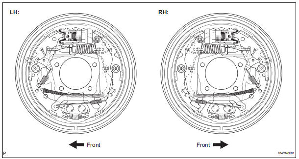
2. INSTALL LH, FRONT OR UPPER REAR WHEEL BRAKE CYLINDER ASSEMBLY
(a) Install the rear wheel brake cylinder assembly with the 2 bolts.
Torque: 10 N*m (102 kgf*cm, 7 ft.*lbf) (b) Using SST, connect the brake tube.
SST 09023-00101 Torque: 15 N*m (155 kgf*cm, 11 ft.*lbf)
3. APPLY HIGH TEMPERATURE GREASE
(a) Apply high temperature grease to the shoe attached surface of backing plate.
4. INSTALL REAR BRAKE SHOE
(a) Apply high temperature grease to the adjusting bolt.
(b) Install the rear brake strut set with the shoe return spring.
(c) Using a pliers, install the rear brake strut set, parking brake reaction lever and parking brake shoe lever LH with the 2 new C-washers.
(d) Using a needle-nose pliers, connect the parking brake cable No. 3 to the parking brake shoe lever LH.
(e) Using SST, install the rear brake shoe, pin, shoe hold down spring and shoe hold down spring cup.
SST 09718-00010
5. INSTALL FRONT BRAKE SHOE
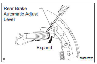
(a) Install the rear brake automatic adjust lever LH, automatic adjust lever spring and parking brake shoe strut LWR to the front brake shoe.
(b) Using SST, install the front brake shoe, pin, shoe hold down spring and shoe hold down spring cup.
SST 09718-00010
(c) Install the tension spring to the front brake shoe and rear brake shoe.
(d) Using a needle-nose pliers, install the return spring.
(e) Using SST, install the shoe return spring to the front brake shoe.
SST 09921-00010
6. CHECK REAR DRUM BRAKE INSTALLATION
(a) Check that each part is installed properly.
(b) Measure the brake drum inside diameter and the diameter of the brake shoes. Check that difference between the diameter is the correct shoe clearance.
Shoe clearance: 0.5 mm (0.020 in.)
NOTICE: There should be no oil or grease adhering to the friction surfaces of the shoe lining and the drum.
7. INSTALL REAR BRAKE DRUM SUB-ASSEMBLY
8. ADJUST REAR DRUM BRAKE SHOE CLEARANCE
(a) Temporarily install the hub nuts.
(b) Remove the hole plug, and turn the adjuster and expand the shoe until the drum locks.
(c) Using a screwdriver, back off the adjuster 15 notches.
(d) Install the hole plug.
9. FILL RESERVOIR WITH BRAKE FLUID (See page BR- 3)
10. BLEED BRAKE MASTER CYLINDER (See page BR-3)
11. BLEED BRAKE LINE (See page BR-4)
12. BLEED BRAKE ACTUATOR (w/ VSC) (See page BR- 4)
13. CHECK FLUID LEVEL IN RESERVOIR (See page BR- 7)
14. CHECK BRAKE FLUID LEAKAGE
15. INSTALL REAR WHEEL Torque: 103 N*m (,050 kgf*cm, 76 ft.*lbf)
16. INSPECT PARKING BRAKE PEDAL TRAVEL
17. ADJUST PARKING BRAKE PEDAL TRAVEL
 Inspection
1. INSPECT BRAKE DRUM INSIDE DIAMETER
(a) Using a brake drum gauge or equivalent, measure
the inside diameter of the drum.
Standard inside diameter:
254.0 mm (10.00 in.)
Maximum inside diamet ...
 Parking brake
...
Other materials:
Short in Front Pretensioner Squib LH Circuit
DTC B0135/73 Short in Front Pretensioner Squib LH Circuit
DESCRIPTION
The front pretensioner squib LH circuit consists of the center airbag sensor
assembly and the front seat
outer belt assembly LH.
This circuit instructs the SRS to deploy when deployment conditions are met.
DTC B0135/73 ...
Inspection
1. INSPECT FRONT SPEED SENSOR
(a) Make sure that there is no looseness at the
connector lock part and connecting part of the
connector.
(b) Disconnect the speed sensor connector.
(c) Measure the resistance between terminals 1 and 2
of the speed sensor connector.
OK:
Resistance:
0.92 ...
Front Occupant Classification Sensor RH Collision
Detection
DTC B1786 Front Occupant Classification Sensor RH Collision
Detection
DESCRIPTION
DTC B1786 is output when the occupant classification ECU receives a collision
detection signal sent by
the front occupant classification sensor RH if an accident occurs.
DTC B1786 is also output when the front ...
