Toyota Sienna Service Manual: Reassembly
1. INSTALL 2ND BRAKE PISTON O-RING
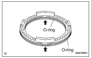
(a) Coat 2 new O-rings with ATF, and install them in the 2nd brake piston.
NOTICE: Make sure that the O-ring is not twisted or pinched.
2. INSTALL 2ND BRAKE PISTON
(a) Coat the 2nd brake piston with ATF, and install it to the 2nd brake cylinder.
NOTICE: Be careful not to damage the O-ring.
3. INSTALL 2ND BRAKE PISTON RETURN SPRING SUB-ASSEMBLY
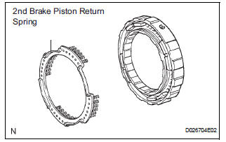
(a) Install the 2nd brake piston return spring.
NOTICE: Installing the spring sub- assembly, check that all of the springs are fit in the piston correctly.
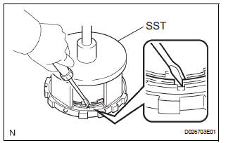
(b) Place SST on the piston return spring, and compress the piston return spring with a press.
SST 09387-00060
(c) Using a screwdriver, install the snap ring.
(d) Be sure that the end gap of the snap ring is not aligned with the spring retainer claw.
NOTICE:
- Stop the press when the spring seat is lowered to the place 1 to 2 mm (0.039 to 0.078 in.) from the snap ring groove.
- This prevents the spring seat from being deformed.
 Inspection
1. INSPECT 2ND BRAKE PISTON RETURN SPRING
SUB-ASSEMBLY
(a) Using vernier calipers, measure the free length of
the spring together with the spring seat.
Standard free length:
16.61 mm (0.6539 ...
 Forward clutch
Components
...
Other materials:
Installation
1. INSTALL NO.1 NAVIGATION BRACKET
Install the No.1 navigation bracket with the 4
screws.
2. INSTALL NO.2 NAVIGATION BRACKET
Install the No.2 navigation bracket with the 4
screws.
3. INSTALL INSTRUMENT CLUSTER FINISH PANEL UPPER
Install the instrum ...
Receiving a message
When an e-mail/SMS/MMS is received, the incoming message screen
pops up with sound and is ready to be operated on the screen.
Select to check the message.
Select to refuse the message.
Select to call the message
sender.
Receiving a message
Depending on the cellular phone used f ...
Radio Receiver Power Source Circuit
DESCRIPTION
This circuit provides power to the radio receiver.
WIRING DIAGRAM
INSPECTION PROCEDURE
1 INSPECT RADIO RECEIVER ASSEMBLY
Disconnect the radio receiver connector.
Measure the resistance according to the value in the
table below.
Standard resistance
Measure t ...
