Toyota Sienna Service Manual: Reassembly
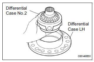
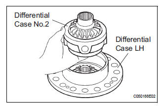
1. INSTALL DIFFERENTIAL CASE SUB-ASSEMBLY NO.2
(a) Coat the front differential side gear thrust washer No.1, front differential planetary ring gear, front differential pinion No.2, front differential pinion thrust washer No.2, front differential pinion shaft holder, front differential pinion shaft and 2 differential pinion shafts with ATF, install them to the differential case No.2.
(b) Using a pin punch and a hammer, install 3 straight pins.
(c) Using a snap ring expander, install the pinion shaft spacer snap ring.
2. INSPECT FRONT DIFFERENTIAL
HINT: (See page AX-276)
3. INSTALL CTR DIFFERENTIAL PLANETARY GEAR ASSEMBLY
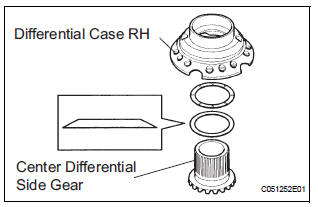
(a) Install the center differential side gear, conical spring washer and center differential side gear thrust washer No.2 RH from the differential case RH.
HINT: Ensure that the conical washers is installed correctly.
(b) Hold the differential case RH by vice. Install the center differential pinion and pinion thrust washer to the differential spider and install them to the differential case RH.
NOTICE: When holding the differential case RH by vise, be sure to place an aluminum sheet between them and use a minimum force
(c) Pressing and holding the differential spider toward the differential case RH, measure the pinion's backlash with a dial indicator as illustrated.
Standard backlash: 0.05 - 0.20 mm (0.0020 - 0.0079 in.)
If the backlash is not within the specified value, refer to the table below and select a thrust washer which will ensure that the backlash is within the specified value.
Thrust washer thickness: mm (in.)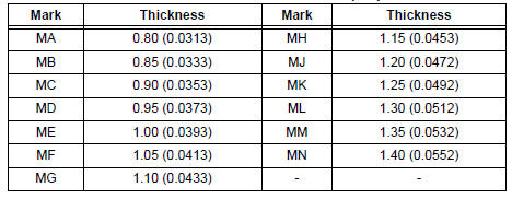
(d) Temporarily install the differential side gear thrust washer No.2 LH, center differential side gear conical spring washer and differential case No.2 to the differential case LH.
HINT: Ensure that the conical washers is installed correctly.
(e) Install the differential intermediate case to the above and fix them with 4 bolts.
(f) remove the differential spider, 5 center differential pinions and 5 center differential pinion thrust washers from the differential case RH. Put them in the differential intermediate case and fix the case.
(g) Pressing and holding the differential spider toward the differential intermediate case, measure the pinion's backlash with a dial indicator.
Standard backlash: 0.05 - 0.20 mm (0.0020 - 0.0079 in.)
If the backlash is not within the specified value, refer to the table below and select a thrust washer which will ensure that the backlash is within the specified value.
Thrust washer thickness: mm (in.)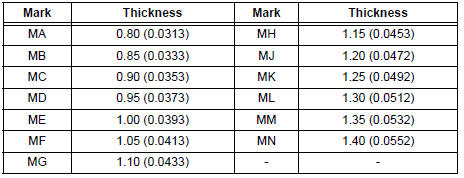
(h) Remove the 4 bolts and disconnect the differential case LH from the differential intermediate case.
(i) Remove the differential case No.2 from the differential case LH.
(j) Install the selected differential side gear thrust washer No.2 LH and center differential planetary gear to the differential case LH.
(k) Install the differential case No.2 to the differential case LH again.
(l) install the adjusted differential case RH to the intermediate case and tighten the 15 bolts using a torx socket wrench(T50).
Torque: 63 N*m (642 kgf*cm, 46 ft.*lbf)
NOTICE: Align the matchmarks.
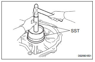
4. INSTALL FRONT DIFFERENTIAL CASE FRONT TAPERED ROLLER BEARING
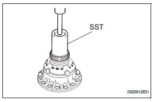
(a) Using SST and a press, install the front differential case tapered roller bearing FR to the differential case.
SST 09950-70010 (09951-07100), 09649-17010
NOTICE: Do not make a damage on the bearing cage during the bearing inner race installation.
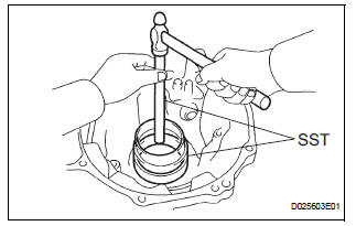
(b) Using SST, install the outer race of the tapered roller bearing FR
SST 09527-17011, 09950-60020 (09951-01030)
NOTICE: Clearance is not allowed between the plate washer and transaxle housing.
5. INSTALL FRONT DIFFERENTIAL SIDE GEAR
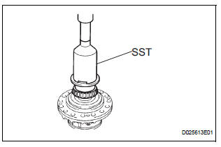
(a) Using SST and a press, install the front differential case tapered roller bearing RR to the differential case.
SST 09316-20011, 09214-76011
NOTICE: Do not make a damage on the bearing cage during the bearing inner race installation.
(b) Install the front differential case shim RR to the transaxle case.
If the bearing is new, check to select a front differential case shim RR of proper thickness starting from the thinner ones. If the bearing is reused, check to select a front differential case shim RR starting from the same thickness as one installed before disassembly.
(c) Using SST, install the outer race of the front differential case tapered roller bearing RR.
SST 09950-60020 (09951-00890), 09950-70010 (09951-07100)
NOTICE: Clearance is not allowed between the differential case shim and transaxle case.
6. ADJUST TAPERED ROLLER BEARING PRELOAD
HINT: (See page AX-279)
7. INSTALL FRONT DIFFERENTIAL RING GEAR
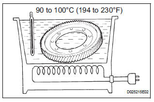
(a) Using ATF and heater, heat the front differential ring gear to 90 to 110°C (194.0 to 230.0°F).
NOTICE: Do not heat the ring gear to more than 110°C (230.0°F).
(b) Clean the contact surface of the front differential case.
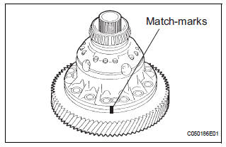
(c) Set the match-marks, install the front differential ring gear case quickly.
NOTICE: Do not install the bolts while the ring gear is hot.
(d) Temporarily install the 8 bolts as shown in the illustration.
(e) Remove the 4 bolts shown in the illustration.
(f) Temporarily install the remaining 8 set bolts.
(g) Fully tighten the set bolts.
Torque: 95.1 N*m (970 kgf*cm, 70 ft.*lbf)
NOTICE: Tighten the bolts a little at a time in diagonal order.
8. INSTALL DIFFERENTIAL SIDE BEARING RETAINER OIL SEAL
(a) Using SST and a hammer, install a new oil seal.
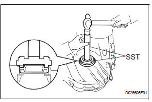
SST 09223-15020, 09950-70010 (09951-07100)
(b) Coat the rip of oil seal with a little MP grease.
9. INSTALL TRANSAXLE HOUSING OIL SEAL
(a) Wind a vinyl tape around SST at the place 6.0 mm (0.236 in.) above from the bottom end until the thickness of the wound tape is about 5.0 mm (0.197 in.).
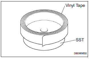
SST 09950-60020 (09951-00730)
NOTICE: Remove foreign matter such as grease on the SST before winding the tape.
(b) Coat the rip of oil seal with a little MP grease.
(c) Using SST, install a new oil seal.
SST 09950-60020 (09951-00730), 09950-70010 (09951-07150) Standard press in depth: 5.5 - 6.5 mm (0.217 - 0.256 in.)
NOTICE: Stop pressing when the would vinyl tape is contact with the transaxle housing.
 Inspection
1. INSPECT FRONT DIFFERENTIAL
(a) Using a dial indicator, measure the backlash of one
pinion gear while holding the front differential side
gear toward the case.
Standard backlash:
0.05 - 0.2 ...
Other materials:
Diagnostic trouble code chart
If a malfunction code is displayed during the DTC check,
check the circuit listed for that code in the table below.
(Proceed to the page given for that circuit.)
BACK DOOR CLOSER SYSTEM
DTC No.
Detection Item
Trouble Area
B2215
Back Door Closer Switch
...
Stereo Component Amplifier Communication Error
INSPECTION PROCEDURE
1 IDENTIFY THE COMPONENT SHOWN BY THE SUB-CODE
Enter the diagnostic mode.
Press the preset switch "3" to change to "Detailed
Information Mode".
Identify the component shown by the sub-code.
HINT:
"190 (radio receiver ...
Occupant Classification Sensor Power Supply
Circuit Malfunction
DTC B1793 Occupant Classification Sensor Power Supply
Circuit Malfunction
DESCRIPTION
The occupant classification sensor power supply circuit consists of the
occupant classification ECU and
the occupant classification sensors.
DTC B1793 is recorded when a malfunction is detected in the occu ...
