Toyota Sienna Service Manual: Removal
1. Remove rear wheel
2. Remove skid control sensor wire (for 2wd)
Hint: (see page sp-38) hint: disconnect the rh side by the same procedures as the lh side.
3. SEPARATE SPEED SENSOR REAR LH (for 4WD)
HINT: (See page SP-38)
4. SEPARATE SPEED SENSOR REAR RH (for 4WD)
HINT: Separate the RH side by the same procedures as the LH side.
5. REMOVE EXHAUST PIPE ASSEMBLY TAIL
HINT:
- 2WD DRIVE TYPE (See page EX-2)
- 4WD DRIVE TYPE (See page EX-8)
6. REMOVE PROPELLER W/CENTER BEARING SHAFT ASSEMBLY (for 4WD)
HINT: (See page PR-2)
7. REMOVE REAR AXLE SHAFT LH NUT (for 4WD)
HINT: (See page AH-18)
8. REMOVE REAR AXLE SHAFT RH NUT (for 4WD)
HINT: Remove the RH side by the same procedures as the LH side.
9. REMOVE REAR DRIVE SHAFT ASSEMBLY LH (for 4WD)
HINT: (See page AH-18)
10. REMOVE REAR DRIVE SHAFT ASSEMBLY RH (for 4WD)
HINT: Remove the RH side by the same procedures as the LH side.
11. REMOVE DIFFERENTIAL CARRIER ASSEMBLY REAR (for 4WD)
HINT: (See page DF-8)
12. SEPARATE PARKING BRAKE CABLE ASSEMBLY NO.3
HINT: (See page SP-38)
13. SEPARATE PARKING BRAKE CABLE ASSEMBLY NO.2
HINT: Separate the RH side by the same procedures as the LH side.
14. SEPARATE REAR BRAKE TUBE NO.2
HINT: (See page SP-38) SST 09023-00101
15. SEPARATE REAR BRAKE TUBE NO.1 SST 09023-00101
HINT: Separate the RH side by the same procedures as the LH side.
16. REMOVE FUEL TANK FILLER HOSE COVER
HINT: (See page SP-38)
17. REMOVE REAR FLOOR NO.2 CROSSMEMBER BRACE LH
HINT: (See page SP-38)
18. REMOVE REAR FLOOR NO.2 CROSSMEMBER BRACE RH
HINT: Remove the RH side by the same procedures as the LH side.
19. LOOSEN REAR AXLE BEAM ASSEMBLY
HINT: (See page SP-38)
20. SEPARATE REAR DISC BRAKE CALIPER ASSEMBLY LH (for DISC REAR BRAKE)
(a) Remove the 2 bolts and separate the rear disc brake caliper assembly LH.
21. SEPARATE REAR DISC BRAKE CALIPER ASSEMBLY RH (for DISC REAR BRAKE)
HINT: Separate the RH side by the same procedures as the LH side.
22. REMOVE REAR DISC (for DISC REAR BRAKE)
23. REMOVE REAR BRAKE DRUM SUB-ASSEMBLY (for DRUM REAR BRAKE)
24. REMOVE REAR AXLE HUB & BEARING ASSEMBLY LH (for 2WD)
HINT: (See page AH-15)
25. REMOVE REAR AXLE HUB & BEARING ASSEMBLY RH (for 2WD)
HINT: Remove the RH side by the same procedures as the LH side.
26. REMOVE REAR AXLE HUB & BEARING ASSEMBLY LH (for 4WD)
HINT: (See page AH-18)
27. REMOVE REAR AXLE HUB & BEARING ASSEMBLY RH (for 4WD)
HINT: Remove the RH side by the same procedures as the LH side.
28. REMOVE PARKING BRAKE PLATE SUB-ASSEMBLY LH (for DISC REAR BRAKE)
(a) 2WD DRIVE TYPE: Remove the rear axle bearing retainer inner LH and parking brake plate subassembly LH.
(b) 4WD DRIVE TYPE: Remove the rear axle bearing retainer outer and parking brake plate sub-assembly LH.
29. REMOVE PARKING BRAKE PLATE SUB-ASSEMBLY RH (for DISC REAR BRAKE)
HINT: Remove the RH side by the same procedures as the LH side.
30. REMOVE BRAKE BACKING PLATE SUB-ASSEMBLY LH (DRUM REAR BRAKE)
(a) Remove the 2 rear axle bearing retainer inner LH and parking brake plate sub-assembly LH.
31. REMOVE BRAKE BACKING PLATE SUB-ASSEMBLY RH (for DRUM REAR BRAKE)
HINT: Remove the RH side by the same procedures as the LH side.
32. SEPARATE SHOCK ABSORBER ASSEMBLY REAR LH
HINT: (See page SP-38)
33. SEPARATE SHOCK ABSORBER ASSEMBLY REAR RH
HINT: Separate the RH side by the same procedures as the LH side.
34. REMOVE COIL SPRING REAR LH
HINT: (See page SP-38)
35. REMOVE COIL SPRING REAR RH
HINT: Remove the RH side by the same procedures as the LH side.
36. REMOVE REAR AXLE BEAM ASSEMBLY
(a) Support the rear axle beam assembly with a jack.
(b) Remove the 2 bolts and 2 nuts.
(c) Remove the rear axle beam assembly.
NOTICE: When loosening the bolt, hold the nut not to rotate.
37. REMOVE REAR BRAKE TUBE FLEXIBLE HOSE
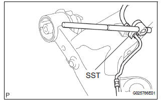
(a) Using SST, separate the brake tube from the flexible hose.
SST 09023-00101 (b) Remove the clip and flexible hose.
HINT: Remove the RH side by the same procedures as the LH side.
38. REMOVE REAR AXLE CARRIER BUSH LH
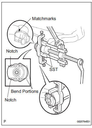
(a) Place matchmarks on the 2 notches of the bushing and rear axle beam assembly.
(b) Using a chisel and hammer, bend the 2 portions of the bushing rib.
HINT: Bend the bushing rib until the claw of SST can be hung.
(c) Using SST, remove the bushing from the rear axle beam assembly.
SST 09950-40011 (09951-04020, 09952-04010, 09953-04030, 09954-04020, 09955-04051, 09957-04010, 09958-04011), 09950-60010 (09951-00630)
NOTICE: If there is a scratch on the axle beam, paint it.
39. REMOVE REAR AXLE CARRIER BUSH RH
SST 09950-40011 (09951-04020, 09952-04010, 09953-04030, 09954-04020, 09955-04051, 09957-04010, 09958-04011), 09950-60010 (09951-00630)
HINT: Remove the RH side by the same procedures as the LH side.
40. REMOVE REAR AXLE BEAM DAMPER
(a) Remove the rear axle beam damper from the rear axle beam assembly.
 Rear axle beam
COMPONENTS
...
 Installation
1. INSTALL REAR AXLE BEAM DAMPER
(a) Install the rear axle beam damper to the rear axle
beam assembly.
2. INSTALL REAR AXLE CARRIER BUSH LH
(a) Align the matchmarks on the axle beam assembly
...
Other materials:
Knock Sensor 1 Circuit Low Input
DESCRIPTION
A flat type knock sensor (non-resonant type) has a structure that can detect
vibrations over a wide band of
frequencies: between approximately 6 kHz and 15 kHz.
Knock sensors are fitted onto the engine block to detect engine knocking.
The knock sensor contains a piezoelectr ...
Past record
Type A
Press the “CAR” button.
Type B
Press the “APPS” button, and then select “Eco” on the screen.
If the “Trip Information” screen is displayed, select “Past Record”.
Reset the past record data
Best recorded fuel consumption
Average fuel consumption ...
Occupant Classification Sensor Power Supply
Circuit Malfunction
DTC B1793 Occupant Classification Sensor Power Supply
Circuit Malfunction
DESCRIPTION
The occupant classification sensor power supply circuit consists of the
occupant classification ECU and
the occupant classification sensors.
DTC B1793 is recorded when a malfunction is detected in the occu ...
