Toyota Sienna Service Manual: Occupant Classification System Malfunction
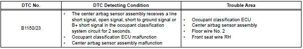
DTC B1150/23 Occupant Classification System Malfunction
DESCRIPTION
The occupant classification system circuit consists of the center airbag sensor assembly and the occupant classification ECU.
If the center airbag sensor assembly receives signals from the occupant classification ECU, it determines whether or not the front passenger airbag, the front seat side airbag RH, and front seat belt pretensioner RH should be operated.
DTC B1150/23 is recorded when a malfunction is detected in the occupant classification system circuit.
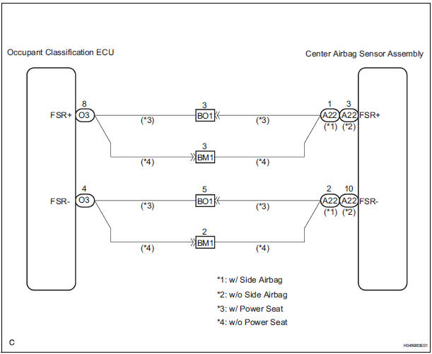
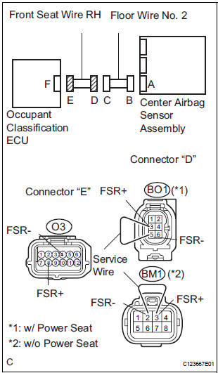
WIRING DIAGRAM
INSPECTION PROCEDURE
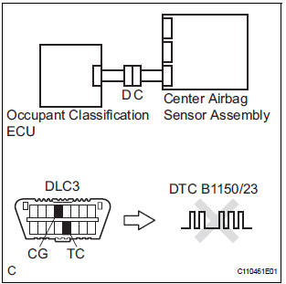
1 CHECK DTC (OCCUPANT CLASSIFICATION ECU)
- Turn the ignition switch to the ON position, and wait for at least 10 seconds.
- Using the intelligent tester, check the DTCs of the occupant classification ECU.
OK: DTC is not output
2 CHECK DTC (CENTER AIRBAG SENSOR ASSEMBLY)
- Turn the ignition switch to the ON position, and wait for at least 60 seconds.
- Clear the DTCs stored in memory.
- Turn the ignition switch to the LOCK position.
- Turn the ignition switch to the ON position, and wait for at least 60 seconds.
- Check the DTCs.
OK: DTC B1150/23 is not output.
HINT: Codes other than code B1150/23 may be output at this time, but they are not related to this check.
USE SIMULATION METHOD TO CHECK
3 CHECK CONNECTION OF CONNECTORS
- Turn the ignition switch to the LOCK position.
- Disconnect the negative (-) terminal cable from the battery, and wait for at least 90 seconds.
- Check that the connectors are properly connected to the center airbag sensor assembly and the occupant classification ECU.
OK: The connectors are connected.
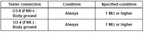
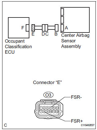
4 CHECK OCCUPANT CLASSIFICATION ECU CIRCUIT (SHORT TO GROUND)
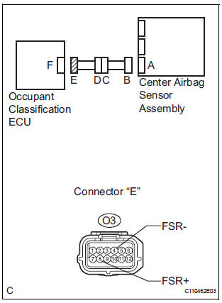
- Disconnect the connectors from the center airbag sensor assembly and the occupant classification ECU.
- Measure the resistance according to the value(s) in the table below.
Standard resistance
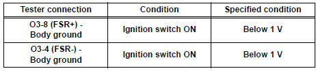
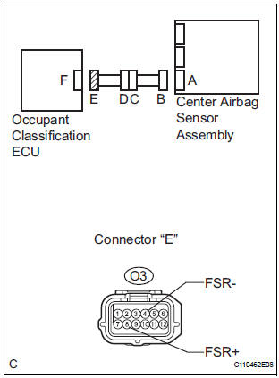
5 CHECK OCCUPANT CLASSIFICATION ECU CIRCUIT (SHORT TO B+)
- Connect the negative (-) terminal cable to the battery, and wait for at least 2 seconds.
- Turn the ignition switch to the ON position.
- Measure the voltage according to the value(s) in the table below.
Standard voltage
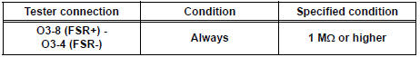
6 CHECK OCCUPANT CLASSIFICATION ECU CIRCUIT (SHORT)
- Turn the ignition switch to the LOCK position.
- Disconnect the negative (-) terminal cable from the battery, and wait for at least 90 seconds.
- Measure the resistance according to the value(s) in the table below.
Standard resistance
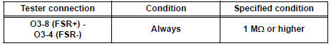
7 CHECK OCCUPANT CLASSIFICATION ECU CIRCUIT (OPEN)
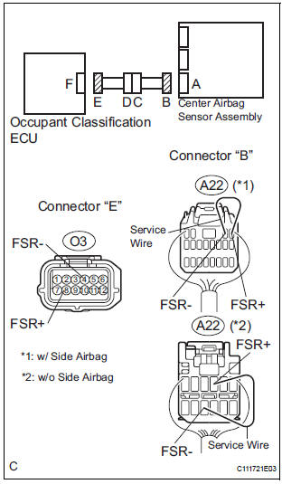
- w/ Side airbag:
Using a service wire, connect A22-1 (FSR+) and A22-2
(FSR-) of connector "B".
NOTICE: Do not forcibly insert a service wire into the terminals of the connector when connecting.
- w/o Side airbag:
Using a service wire, connect A22-3 (FSR+) and A22-10
(FSR-) of connector "B".
NOTICE: Do not forcibly insert a service wire into the terminals of the connector when connecting.
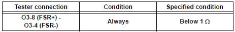
- Measure the resistance according to the value(s) in the table below.
Standard resistance
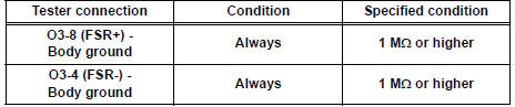
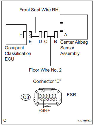
8 CHECK FRONT SEAT WIRE RH (SHORT TO GROUND)
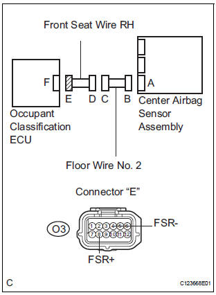
- Disconnect the front seat wire RH connector from the floor wire No. 2.
- Measure the resistance according to the value(s) in the table below.
Standard resistance
REPAIR OR REPLACE FLOOR WIRE NO.2
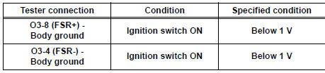
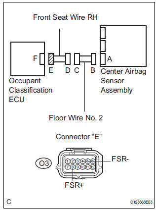
9 CHECK FRONT SEAT WIRE RH (SHORT TO B+)
- Turn the ignition switch to the LOCK position.
- Disconnect the negative (-) terminal cable from the battery, and wait for at least 90 seconds.
- Disconnect the front seat wire RH connector from the floor wire No. 2.
- Connect the negative (-) terminal cable to the battery, and wait for at least 2 seconds.
- Turn the ignition switch to the ON position.
- Measure the voltage according to the value(s) in the table below.
Standard voltage
REPAIR OR REPLACE FLOOR WIRE NO.2
10 CHECK FRONT SEAT WIRE RH (SHORT)
- Disconnect the front seat wire RH connector from the floor wire No. 2.
- Measure the resistance according to the value(s) in the table below.
Standard resistance
REPAIR OR REPLACE FLOOR WIRE NO.2
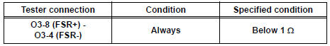
11 CHECK FRONT SEAT WIRE RH (OPEN)
- Disconnect the service wire from connector "B".
- Disconnect the front seat wire RH connector from the floor wire No. 2.
- w/ Power seat:
Using a service wire, connect BO1-3 (FSR+) and BO1-5
(FSR-) of connector "D".
NOTICE: Do not forcibly insert a service wire into the terminals of the connector when connecting.
- w/o Power seat:
Using a service wire, connect BM1-3 (FSR+) and BM1-2
(FSR-) of connector "D".
NOTICE: Do not forcibly insert a service wire into the terminals of the connector when connecting.
- Measure the resistance according to the value(s) in the table below.
Standard resistance
REPAIR OR REPLACE FLOOR WIRE NO.2
 Front Airbag Sensor LH Circuit Malfunction
DTC B1149/37 Front Airbag Sensor LH Circuit Malfunction
DESCRIPTION
The front airbag sensor LH circuit consists of the center airbag sensor
assembly and front airbag sensor
LH.
If the center a ...
 Passenger Airbag ON/OFF Indicator Circuit
Malfunction
Passenger Airbag ON/OFF Indicator Circuit
Malfunction
DTC B1152/28 Passenger Airbag ON/OFF Indicator Circuit
Malfunction
DESCRIPTION
The passenger airbag ON/OFF indicator circuit consists of the center airbag
sensor assembly and
passenger airba ...
Other materials:
Removal
1. REMOVE BATTERY
2. REMOVE AIR CLEANER ASSEMBLY
HINT:
(See page EM-26)
3. REMOVE SPEED SENSOR (NT SENSOR)
(a) Disconnect the speed sensor connector.
(b) Remove the bolt and speed sensor.
4. REMOVE SPEED SENSOR (NC SENSOR)
(a) Disconnect the speed sensor connector.
(b) Remove th ...
Installation
1. INSTALL TRANSAXLE HOUSING OIL SEAL
(a) Using SST and a hammer, install a new oil seal.
SST 09316-60011 (09316-00011)
Oil seal installation depth:
-0.5 to 0.5 mm (-0.020 to 0.020 in.)
(b) Coat the lip of the oil seal with MP grease.
2. INSTALL DIFFERENTIAL SIDE BEARING RETAINER OIL SEA ...
Power window regulator
motor
INSPECTION
1. INSPECT POWER WINDOW REGULATOR MOTOR
(FRONT RH)
Remove the power window regulator motor.
Apply battery voltage to the motor connector
according to the table below.
NOTICE:
Do not apply battery to any terminals except
terminals 1 and 2.
Standard
2. INS ...
