Toyota Sienna Service Manual: Sound Signal Circuit between Radio Receiver and Stereo Jack Adapter
DESCRIPTION
The stereo jack adapter sends an external device sound signal to the radio receiver through this circuit.
The sound signal that has been sent is amplified by the stereo component amplifier or radio receiver, and then is sent to the speakers.
If there is an open or short in the circuit, sound cannot be heard from the speakers even if there is no malfunction in the stereo component amplifier, radio receiver, or speakers.
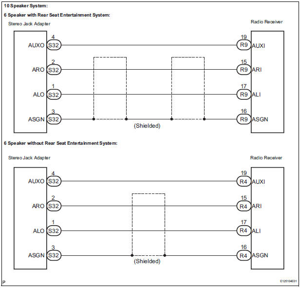
WIRING DIAGRAM
INSPECTION PROCEDURE
1 CHECK HARNESS AND CONNECTOR (RADIO RECEIVER - STEREO JACK ADAPTER)
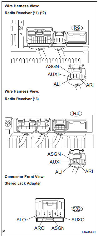
- Disconnect the connectors from the stereo jack adapter and radio receiver.
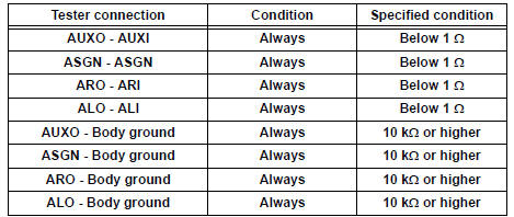
- Measure the resistance according to the value(s) in the table below.
Standard resistance
*1: 10 Speaker System
*2: 6 Speaker with Rear Entertainment System
*3: 6 Speaker without Rear Entertainment System
PROCEED TO NEXT CIRCUIT INSPECTION SHOWN IN PROBLEM SYMPTOMS TABLE
 Sound Signal Circuit between Radio Receiver and Television Display
Assembly
Sound Signal Circuit between Radio Receiver and Television Display
Assembly
DESCRIPTION
The television display assembly sends a sound signal to the radio receiver
through this circuit.
The sound signal that has been sent is amplified by the stereo component
amplifier ...
 Mute Signal Circuit between Radio Receiver and Stereo Component
Amplifier
Mute Signal Circuit between Radio Receiver and Stereo Component
Amplifier
DESCRIPTION
This circuit sends a signal to the stereo component amplifier to mute noise.
Because of that, the noise
produced by changing the sound source ceases.
If there is an open in the circ ...
Other materials:
Radar Sensor Malfunction
DTC P1570 Radar Sensor Malfunction
DESCRIPTION
The laser sensor emits laser beams towards an object in front and measures
the distance and direction of
the object by receiving the beam reflections. Based on the reflections, the
sensor calculates the difference
in speed between your own vehic ...
Occupant Classification Sensor Power Supply
Circuit Malfunction
DTC B1793 Occupant Classification Sensor Power Supply
Circuit Malfunction
DESCRIPTION
The occupant classification sensor power supply circuit consists of the
occupant classification ECU and
the occupant classification sensors.
DTC B1793 is recorded when a malfunction is detected in the occu ...
Registration
NOTICE:
The Vehicle Identification Number (VIN) must be input
into the replacement ECM.
HINT:
The VIN is a 17-digit alphanumeric vehicle identification
number. The intelligent tester is required to register the VIN.
1. INPUT INSTRUCTIONS
The general VIN input instructions using the
...
