Toyota Sienna Service Manual: Removal
HINT:
- Don't use the dropped or damaged yawrate sensor
- Free from the foreign matters between yaerate sensor bracket and body.
- Make sure the sensor direction.
1. REMOVE FRONT SEAT ASSEMBLY RH
HINT: See page SE-40.
2. REMOVE FRONT DOOR SCUFF PLATE RH
3. REMOVE COWL SIDE TRIM BOARD RH
(a) Remove the nut and cowl side trim board plate RH.
4. REMOVE YAW RATE AND DECELERATION SENSOR
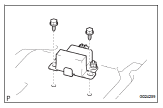
(a) Disconnect the yawrate sensor connector.
(b) Remove the 2 bolts and yawrate sensor.
 Yaw rate and deceleration sensor
Components
...
 Installation
1. INSTALL YAW RATE AND DECELERATION SENSOR
(a) Connect the yawrate sensor connector.
(b) Install the yawrate sensor with the 2 bolts.
Torque: 13 N*m (136 kgf*cm, 10 ft.*lbf)
2. INSTALL COWL ...
Other materials:
Installation
1. Connect inlet sub-assembly
(a) Connect the inlet hose to the radiator.
(b) Install the inlet sub-assembly to the radiator with the
bolt.
Torque: 7.1 N*m (72 kgf*cm, 63 in.*lbf)V
2. Install no. 2 Radiator support
(A) install the no. 2 Radiator support to the radiator with
the 2 ...
Power outlets
The power outlet can be used for the following components:
12 V: Accessories that run on less than 10 A
120 V AC: Accessories that use less than 100 W
12 V
Open the cover.
Center panel type A
Center panel type B
Luggage compartment
120 V AC (if equipped)
Open the ...
Removal
1. REMOVE INSTRUMENT CLUSTER CENTER NO. 1 FINISH PANEL
2. REMOVE INSTRUMENT CLUSTER CENTER NO. 2
FINISH PANEL
3. REMOVE SHIFT LEVER KNOB SUB-ASSEMBLY
4. REMOVE POSITION INDICATOR HOUSING ASSEMBLY
5. REMOVE INSTRUMENT CLUSTER CENTER LOWER FINISH PANEL SUB-ASSEMBLY
6. REMOVE CIGARETTE LIGHTER CO ...
