
Toyota Sienna Service Manual: Yaw rate and deceleration sensor
Components
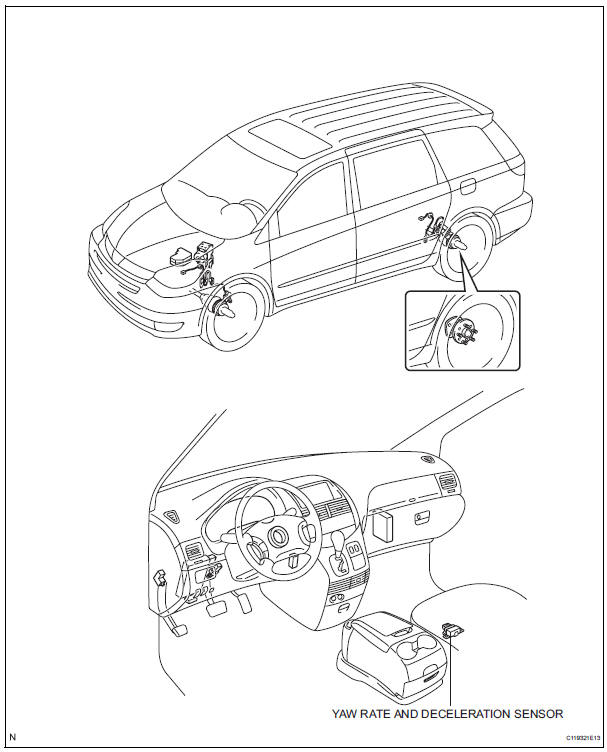
 Installation
HINT:
Install the RH side by same procedure as the LH side.
1. INSTALL REAR SPEED SENSOR
(a) Install the speed sensor rear LH with the bolt.
Torque: 8.0 N*m (82 kgf*cm, 71 in.*lbf)
NOTICE:
K ...
 Removal
HINT:
Don't use the dropped or damaged yawrate sensor
Free from the foreign matters between yaerate sensor
bracket and body.
Make sure the sensor direction.
1. REMOVE FRONT SEAT ASSEMBLY ...
Other materials:
TC and CG Terminal Circuit
DESCRIPTION
DTC output mode is set by connecting terminals 13 (TC) and 4 (CG) of the
DLC3. The DTCs are indicated
by blinks of the tire pressure warning light.
WIRING DIAGRAM
HINT:
When each warning light blinks continuously, a ground short in the wiring of
terminal TC of the DLC3 or an ...
Sound Signal Circuit between Radio and Navigation Assembly and
Stereo Component Amplifier
DESCRIPTION
The radio and navigation assembly sends a sound signal to the stereo
component amplifier through this
circuit.
The sound signal that has been sent is amplified by the stereo component
amplifier, and then is sent to
the speakers.
If there is an open or short in the circuit, s ...
Removal
1. DISCONNECT CABLE FROM NEGATIVE BATTERY
TERMINAL
2. REMOVE ENGINE UNDER COVER NO.1
3. DRAIN AUTOMATIC TRANSAXLE FLUID
(a) Remove the drain plug and gasket, and drain the
ATF.
(b) Install a new gasket and the drain plug.
Torque: 49 N*m (500 kgf*cm, 36 ft.*lbf)
4. REMOVE AUTOMATIC TRANSA ...
