Toyota Sienna Service Manual: Removal
HINT: For the parking brake cable assembly No. 2, perform the same procedure to the parking brake cable assembly No. 3.
1. REMOVE REAR WHEEL
2. REMOVE REAR BRAKE DRUM SUB-ASSEMBLY (for Drum Type) (See page BR-37)
3. REMOVE FRONT BRAKE SHOE (for Drum Type) (See page BR-37)
4. REMOVE REAR BRAKE SHOE (for Drum Type) (See page BR-38)
5. SEPARATE REAR DISC BRAKE CALIPER ASSEMBLY LH (for Disc Type) (See page PB-15)
6. REMOVE REAR DISC (for Disc Type) (See page BR- 32)
7. REMOVE PARKING BRAKE SHOE ASSEMBLY LH NO.1 (for Disc Type) (See page PB-15)
8. REMOVE PARKING BRAKE SHOE ADJUSTING SCREW SET (for Disc Type)
9. REMOVE PARKING BRAKE SHOE STRUT LH (for Disc Type)
10. REMOVE PARKING BRAKE SHOE ASSEMBLY LH NO.2 (for Disc Type) (See page PB-15)
11. SEPARATE PARKING BRAKE CABLE ASSEMBLY NO.3
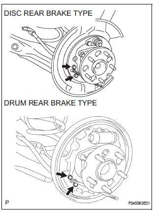
(a) Remove the 2 bolts, and disconnect the parking brake cable No. 3 from the backing plate.
12. REMOVE PARKING BRAKE CABLE ASSEMBLY NO.3
(a) Remove the 3 bolts and the button to disconnect the parking brake cable No. 3 from the body.
(b) Disconnect the parking brake cable No. 3 from the parking brake equalizer, and remove the parking brake cable No. 3.
(c) Remove the parking brake cable LH guide from the parking brake cable assembly No. 3.
 Parking brake cable
Components
...
 Installation
1. INSTALL PARKING BRAKE CABLE ASSEMBLY NO.3
(a) Install the parking brake cable LH guide to the
parking brake cable assembly No. 3.
(b) Connect the parking brake cable No. 3 to the
parking brak ...
Other materials:
Short to GND in Curtain Shield Squib RH Circuit
DTC B1162/81 Short to GND in Curtain Shield Squib RH Circuit
DESCRIPTION
The curtain shield squib RH circuit consists of the center airbag sensor
assembly and the curtain shield
airbag assembly RH.
The circuit instructs the SRS to deploy when deployment conditions are met.
DTC B1162/81 is ...
Body
GENERAL MAINTENANCE
1. TIGHTEN BOLTS AND NUTS ON CHASSIS AND
BODY
(a) Tighten all the parts of the chassis when necessary.
Steering system
Drive train
Suspension
Brake system
Engine mounting, etc.
(b) Tighten all the parts of the body when necessary.
Seat belts
Seats
Doors ...
Window lock switch
Press the switch down to lock the
passenger window switches.
Use this switch to prevent children
from accidentally opening or closing
a passenger window.
The power windows can be operated when
The engine switch is in the “ON” position (vehicles without a smart key
system)
or IGNIT ...
