Toyota Sienna Service Manual: Knock sensor
COMPONENTS
REMOVAL
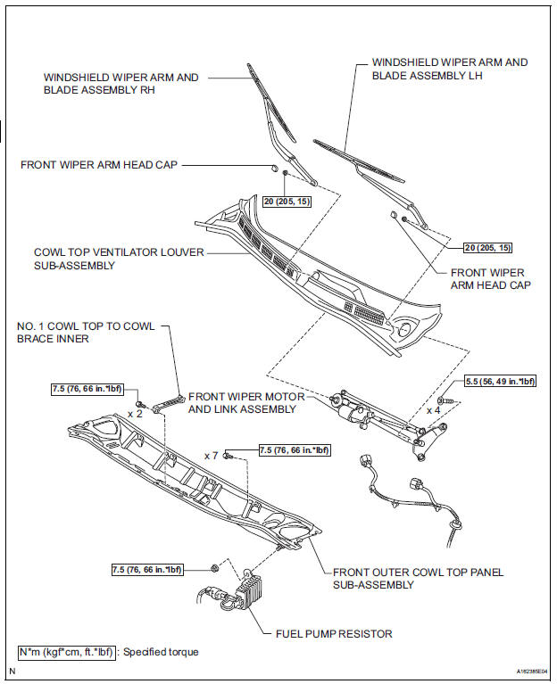
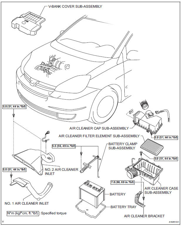
1. DISCHARGE FUEL SYSTEM PRESSURE (See page FU-13) 2. REMOVE V-BANK COVER SUB-ASSEMBLY (See page EM-28) 3. DRAIN ENGINE COOLANT (See page CO-6) 4. REMOVE WINDSHIELD WIPER MOTOR ASSEMBLY HINT: (See page WW-4) 5. REMOVE FRONT OUTER COWL TOP PANEL SUBASSEMBLY (See page EM-27) 6. REMOVE AIR CLEANER CAP SUB-ASSEMBLY (See page ES-493) 7. REMOVE AIR CLEANER CASE SUB-ASSEMBLY (See page EM-28) 8. REMOVE INTAKE AIR SURGE TANK ASSEMBLY
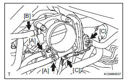
(a) Disconnect the 2 water by-pass hoses from the throttle body [A].
(b) Disconnect the vapor feed hose [B].
(c) Disconnect the throttle body connector and clamp [C].
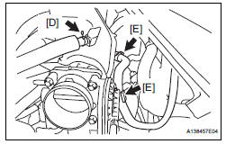
(d) Disconnect the ventilation hose [D].
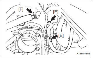
(e) Disconnect the union to check valve hose [E].
(f) Disconnect the connector [F].
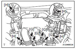
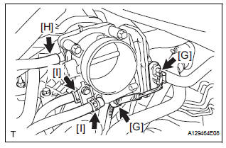
(g) Using a 5 mm socket hexagon wrench, remove the 4 bolts [G].
(h) Remove the 2 nuts, 2 bolts and intake air surge tank [H].
(i) Remove the gasket from the intake air surge tank [I].
9. REMOVE FUEL MAIN TUBE SUB-ASSEMBLY (See page EM-30) 10. REMOVE INTAKE MANIFOLD (See page EM-39)
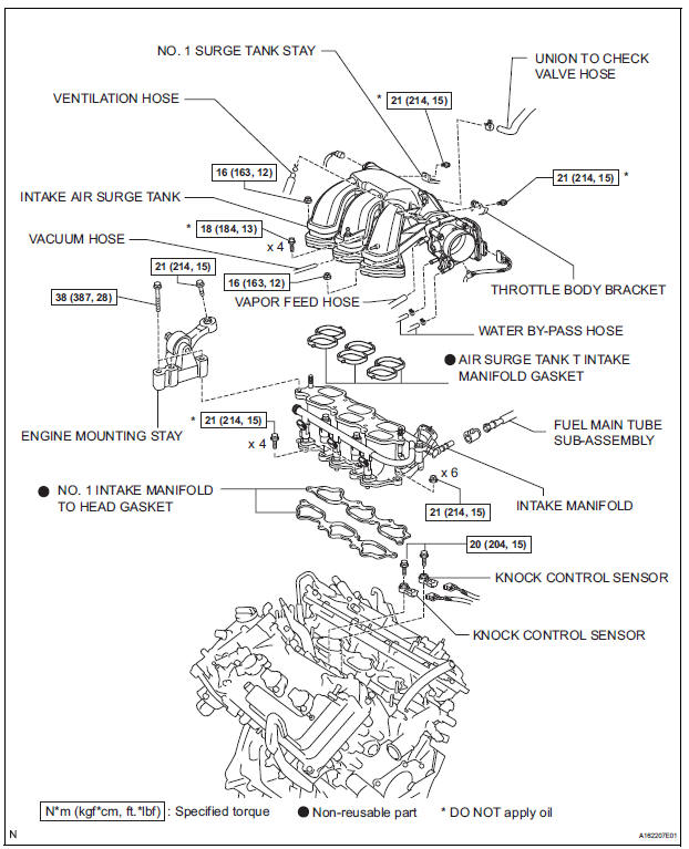
11. REMOVE KNOCK CONTROL SENSOR
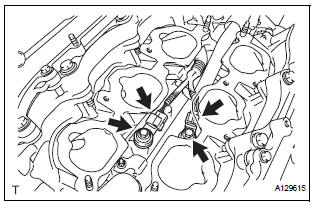
(a) Disconnect the 2 knock sensor connectors.
(b) Remove the 2 bolts and then remove the 2 knock control sensors.
INSPECTION
1. KNOCK CONTROL SENSOR
(a) Using an ohmmeter, measure the resistance between the terminals.
Resistance: 120 to 280 kΩ at 20°C (68°F)
If the resistance is not specified, replace the knock control sensor.
INSTALLATION
1. INSTALL KNOCK CONTROL SENSOR
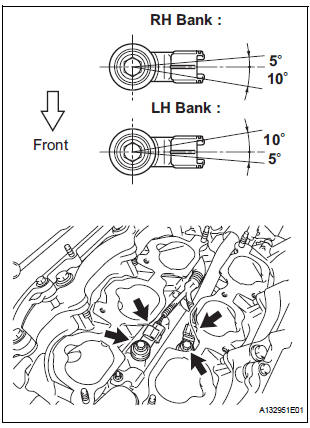
(a) Install the 2 knock control sensors with the 2 bolts as shown in the illustration.
Torque: 20 N*m (204 kgf*cm, 15 ft.*lbf) (b) Connect the 2 knock control sensor connectors.
2. INSTALL INTAKE MANIFOLD (See page EM-49) 3. INSTALL FUEL MAIN TUBE SUB-ASSEMBLY (See page EM-56) 4. INSTALL INTAKE AIR SURGE TANK
| NOTICE: DO NOT apply oil to the bolts listed below. |
(a) Install a new gasket to the intake air surge tank [A].
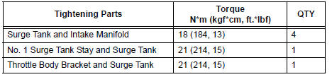
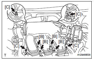
(b) Using a 5 mm hexagon socket wrench, install the 4 bolts [B].
Torque: 18 N*m (184 kgf*cm, 13 ft.*lbf) (c) Install the intake air surge tank with the 2 nuts and 2 bolts [C].
Torque: Nut 16 N*m (163 kgf*cm, 12 ft.*lbf) Bolt 21 N*m (214 kgf*cm, 15 ft.*lbf)
(d) Connect the connector [D].
(e) Connect the union to check valve hose [E].
(f) Connect the ventilation hose No. 2 [F].
(g) Install the clamp and connect the throttle with motor body assembly connector [G].
(h) Connect the vapor feed hose [H].
(i) Connect the 2 water by-pass hoses to the throttle with motor body assembly [I].
5. INSTALL AIR CLEANER CASE SUB-ASSEMBLY (See page EM-59) 6. INSTALL AIR CLEANER CAP SUB-ASSEMBLY (See page ES-496) 7. ADD ENGINE COOLANT (See page CO-7) 8. INSPECT FOR ENGINE COOLANT LEAK (See page CO-1) 9. INSPECT FOR FUEL LEAK (See page FU-7) 10. INSTALL FRONT OUTER COWL TOP PANEL SUBASSEMBLY (See page EM-61) 11. INSTALL WINDSHIELD WIPER MOTOR ASSEMBLY
HINT: (See page WW-5)
12. INSTALL V-BANK COVER SUB-ASSEMBLY (See page EM-63)
 Engine coolant temperature sensor
COMPONENTS
REMOVAL
1. DRAIN ENGINE COOLANT (See page CO-6)
2. REMOVE V-BANK COVER SUB-ASSEMBLY (See
page EM-28)
3. REMOVE NO. 2 AIR CLEANER INLET (See page EM-
28)
4. REMOVE NO. 1 AIR CLEAN ...
 Efi relay
INSPECTION
1. INSPECT EFI RELAY
(a) Using an ohmmeter, measure the resistance
according to the value(s) in the table below.
Standard resistance
If the result is not as specified, replace th ...
Other materials:
Problem symptoms table
HINT:
If a normal code is displayed during the diagnostic trouble
code check although the trouble still occurs, check the
electrical circuits for each symptom in the order given in
the charts on the following pages and proceed to the page
given for troubleshooting.
The Matrix Chart is ...
Rear view monitor
system
The rear view monitor system assists the driver by displaying an
image of the view behind the vehicle and guide lines while backing
up, for example while parking.
The screen illustrations used in this text are intended as examples,
and may differ from the image that is actually displayed on the
...
U151e automatic transaxle
SST
RECOMMENDED TOOLS
EQUIPMENT
LUBRICANT
SSM
...
