Toyota Sienna Service Manual: Parking Brake Switch Circuit
DESCRIPTION
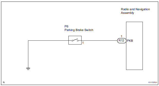
This circuit is from the parking brake switch to the radio and navigation assembly.
WIRING DIAGRAM
INSPECTION PROCEDURE
1 CHECK BRAKE WARNING LIGHT
- Check that the brake warning light comes on when the parking brake is applied and goes off when it is released.
OK: The brake warning light operates as specified above.
2 INSPECT PARKING BRAKE SWITCH
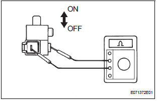
- Disconnect the parking brake switch.
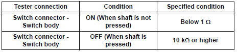
- Measure the resistance according to the value(s) in the table below.
Standard resistance
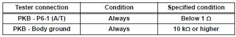
3 CHECK HARNESS AND CONNECTOR (PARKING BRAKE SWITCH - RADIO AND NAVIGATION ASSEMBLY)
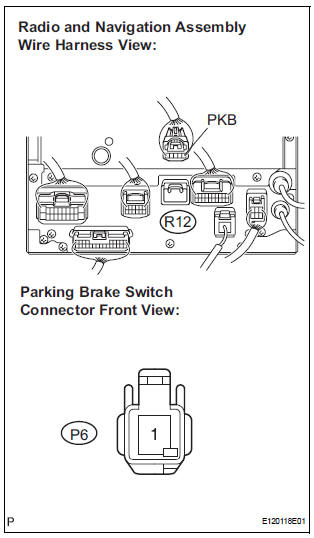
- Disconnect the radio and navigation assembly connector R12 and parking brake switch connector P6.
- Measure the resistance according to the value(s) in the table below.
Standard resistance
PROCEED TO NEXT CIRCUIT INSPECTION SHOWN IN PROBLEM SYMPTOMS TABLE
 Illumination Circuit
DESCRIPTION
Power is supplied to the radio and navigation assembly and steering pad
switch illumination when the
light control switch is in the TAIL or HEAD position.
WIRING DIAGRAM
INSPECTI ...
 Speaker Circuit
DESCRIPTION
The sound signal that has been amplified by the stereo component amplifier is
sent to the speakers from
the stereo component amplifier through this circuit.
If there is a short in t ...
Other materials:
Open in Pump Motor Circuit
DTC C1251/51 Open in Pump Motor Circuit
DESCRIPTION
WIRING DIAGRAM
INSPECTION PROCEDURE
1 PERFORM ACTIVE TEST USING INTELLIGENT TESTER (ABS MOTOR RELAY)
(a) Connect the intelligent tester to the DLC3.
(b) Start the engine.
(c) Select the ACTIVE TEST mode on the intelligent tester.
...
Transmission Fluid Temperature Sensor "A"
DESCRIPTION
The ATF (Automatic Transmission Fluid) temperature sensor converts the fluid
temperature into a
resistance value which is input into the ECM.
The ECM applies a voltage to the temperature sensor through ECM terminal THO1.
The sensor resistance changes with the transmission f ...
Wireless remote control/
electronic key battery
Replace the battery with a new one if it is depleted.
You will need the following items:
Flathead screwdriver
Lithium battery CR2032
Replacing the battery
Vehicles without a smart key system
Remove the cover using a coin
protected with tape etc.
Remove the deplete ...
