Toyota Sienna Service Manual: Installation
1. INSTALL PARKING BRAKE CABLE ASSEMBLY NO.3
(a) Install the parking brake cable LH guide to the parking brake cable assembly No. 3.
(b) Connect the parking brake cable No. 3 to the parking brake cable equalizer.
(c) Install the parking brake cable No. 3 with the 3 bolts and button.
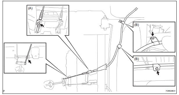
Torque: Bolt (A) 5.4 N*m (55 kgf*cm, 48 in.*lbf) Bolt (B) 8 N*m (82 kgf*cm, 71 in.*lbf)
2. CONNECT PARKING BRAKE CABLE ASSEMBLY NO.3
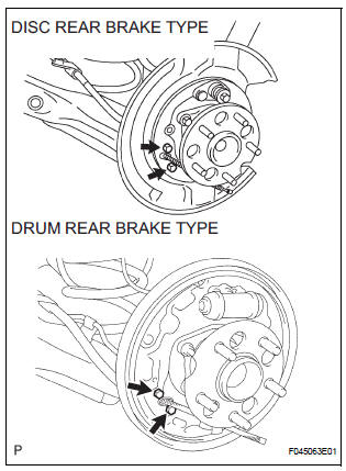
(a) Install the parking brake cable No. 3 with the 2 bolts to the backing plate.
Torque: 8 N*m (82 kgf*cm, 71 in.*lbf)
3. APPLY HIGH TEMPERATURE GREASE (for Drum Type) (See page BR-40)
4. INSTALL REAR BRAKE SHOE (for Drum Type) (See page BR-40)
5. INSTALL FRONT BRAKE SHOE (for Drum Type) (See page BR-40)
6. CHECK REAR DRUM BRAKE INSTALLATION (for Drum Type) (See page BR-42)
7. INSTALL REAR BRAKE DRUM SUB-ASSEMBLY (for Drum Type)
8. ADJUST REAR DRUM BRAKE SHOE CLEARANCE (for Drum Type) (See page BR-42)
9. INSPECT PARKING BRAKE PEDAL TRAVEL (for Drum Type) (See page PB-1)
10. ADJUST PARKING BRAKE PEDAL TRAVEL (for Drum Type) (See page PB-1)
11. APPLY HIGH TEMPERATURE GREASE (for Disc Type) (See page PB-16)
12. INSTALL PARKING BRAKE SHOE ASSEMBLY LH NO.2 (for Disc Type) (See page PB-17)
13. INSTALL PARKING BRAKE SHOE ADJUSTING SCREW SET (for Disc Type)
14. INSTALL PARKING BRAKE SHOE STRUT LH (for Disc Type)
15. INSTALL PARKING BRAKE SHOE ASSEMBLY LH NO.1 (for Disc Type) (See page PB-17)
16. CHECK PARKING BRAKE INSTALLATION (for Disc Type) (See page PB-18)
17. INSTALL REAR DISC (for Disc Type) (See page BR- 33)
18. ADJUST PARKING BRAKE SHOE CLEARANCE (for Disc Type) (See page PB-18)
19. CONNECT REAR DISC BRAKE CALIPER ASSEMBLY LH (for Disc Type) (See page BR-35)
20. INSTALL REAR WHEEL Torque: 103 N*m (1,050 kgf*cm, 76 ft.*lbf)
21. INSTALL PARKING BRAKE PEDAL TRAVEL (See page PB-1)
22. ADJUST PARKING BRAKE PEDAL TRAVEL (See page PB-1)
 Removal
HINT:
For the parking brake cable assembly No. 2, perform the
same procedure to the parking brake cable assembly No. 3.
1. REMOVE REAR WHEEL
2. REMOVE REAR BRAKE DRUM SUB-ASSEMBLY (for
Drum Type) ...
 Parking brake assembly
COMPONENTS
...
Other materials:
Operation check
1. NOTICE WHEN CHECKING THE FOLLOWING
Power door lock/unlock function:
The wireless door lock control function operates
only when the following 3 conditions are met:
No key is inserted in the ignition key cylinder.
All the doors are closed.
The power door lock sys ...
Operation check
1. ILLUMINATED ENTRY SYSTEM OPERATION CHECK
The illuminated entry system is explained below:
Turn the ignition switch OFF, close all the doors,
and set them in the lock condition.
Unlock any door and open any other doors and
check that the room light comes on. Close ...
Manual headlight leveling dial (vehicles with discharge headlights)
The level of the headlight aim can be adjusted according to the number
of passengers and the loading condition of the vehicle.
Raises the level of the headlights
Lowers the level of the headlights
Guide to dial settings
Daytime running light system (if equipped)
Bulb type: To ...
