Toyota Sienna Service Manual: Removal
1. RECOVER REFRIGERANT FROM REFRIGERATION SYSTEM (See page AC-172)
2. REMOVE NO. 2 AIR CLEANER INLET (See page EM- 28)
3. REMOVE FRONT BUMPER ASSEMBLY (See page ET-3)
4. DISCONNECT DISCHARGE HOSE SUB-ASSEMBLY
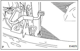
(a) Remove the bolt and disconnect the discharge hose sub-assembly from the cooler condenser core.
(b) Remove the O-ring from the discharge hose subassembly.
NOTICE: Seal the openings of the disconnected parts using vinyl tape to prevent entry of moisture and foreign matter.
5. DISCONNECT COOLER REFRIGERANT LIQUID PIPE A
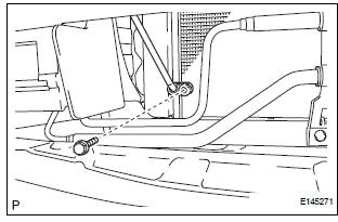
(a) Remove the bolt and disconnect the cooler refrigerant liquid pipe A from the cooler condenser core.
(b) Remove the O-ring from the cooler refrigerant liquid pipe A.
NOTICE: Seal the openings of the disconnected parts using vinyl tape to prevent entry of moisture and foreign matter.
6. REMOVE NO. 1 AIR CLEANER INLET (See page EM- 28)
7. REMOVE HOOD LOCK RELEASE LEVER PROTECTOR (See page CO-29)
8. REMOVE HOOD LOCK ASSEMBLY (See page CO-29)
9. REMOVE HOOD LOCK SUPPORT SUB-ASSEMBLY (See page CO-29)
10. DISCONNECT COOLING FAN ECU CONNECTOR (See page CO-30)
11. REMOVE UPPER RADIATOR SUPPORT SUBASSEMBLY (See page CO-30)
12. DISCONNECT NO. 2 OIL COOLER OUTLET TUBE SUB-ASSEMBLY
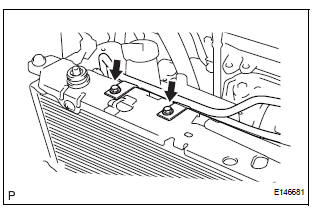
(a) Remove the 2 bolts and No. 2 oil cooler outlet tube sub-assembly.
13. REMOVE RADIATOR SUPPORT CUSHION (See page CO-32)
14. REMOVE NO. 1 RADIATOR SUPPORT (See page CO- 32)
15. REMOVE COOLER CONDENSER CORE

(a) Remove the 2 screws and cooler condenser core.
 On-vehicle inspection
1. INSPECT COOLER CONDENSER CORE
(a) If the fin of the cooler condenser core is dirty, clean
it with water and dry it with compressed air.
NOTICE:
Do not damage the fin of the cooler condenser
co ...
 Disassembly
1. REMOVE COOLER DRYER
(a) Using a hexagon wrench 14 mm (0.55 in.), remove
the cap from the modulator.
(b) Remove the O-ring from the cap.
(c) Using needle nose pliers, remove the cool ...
Other materials:
On-vehicle inspection
1. FRONT SEAT SIDE AIRBAG ASSEMBLY (VEHICLE
NOT INVOLVED IN COLLISION)
Perform a diagnostic system check.
With the front seat side airbag assembly installed on
the vehicle, perform a visual check. If there are any
defects as mentioned below, replace the front
seatback as ...
Reassembly
1. INSTALL DIFFERENTIAL CASE SUB-ASSEMBLY NO.2
(a) Coat the front differential side gear thrust washer
No.1, front differential planetary ring gear, front
differential pinion No.2, front differential pinion thrust
washer No.2, front differential pinion shaft holder,
front differential pinio ...
System description
1. DESCRIPTION OF OCCUPANT CLASSIFICATION SYSTEM
GENERAL DESCRIPTION.
In the occupant classification system, the
occupant classification ECU calculates the
weight of the occupant based on a signal from
the occupant classification sensors. This system
recognizes the occu ...
