Toyota Sienna Service Manual: Removal
1. REMOVE INSTRUMENT CLUSTER CENTER NO. 1 FINISH PANEL
2. REMOVE INSTRUMENT CLUSTER CENTER NO. 2 FINISH PANEL
3. REMOVE INSTRUMENT CLUSTER FINISH PANEL GARNISH
4. REMOVE RADIO RECEIVER
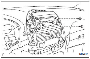
- Remove the 4 screws.
- Disconnect the connectors and remove the radio receiver with bracket.
5. REMOVE RADIO NO. 1 BRACKET
- Remove the 4 screws and radio No. 1 bracket.
6. REMOVE RADIO NO. 2 BRACKET
- Remove the 4 screws and radio No. 2 bracket.
 Radio receiver
COMPONENTS
...
 Installation
1. INSTALL RADIO NO. 2 BRACKET
Install radio No. 2 bracket with the 4 screws.
2. INSTALL RADIO NO. 1 BRACKET
Install radio No. 1 bracket with the 4 screws.
3. INSTALL R ...
Other materials:
Rear Airbag Sensor RH Circuit Malfunction
DTC B1154/38 Rear Airbag Sensor RH Circuit Malfunction
DESCRIPTION
The rear airbag sensor RH circuit consists of the center airbag sensor
assembly and rear airbag sensor
RH.
If the center airbag sensor assembly receives signals from the rear airbag
sensor RH, it judges whether or
not the ...
For vehicles equipped with mobile communication systems
FOR VEHICLES EQUIPPED WITH MOBILE COMMUNICATION SYSTEMS
(a) Install the antenna far away from the ECU and
sensors of the vehicle electronic systems as
possible.
(b) Install an antenna feeder at least 20 cm (7.87 in.)
away from the ECU and sensors of the vehicle
electronic systems. For de ...
Front Occupant Classification Sensor RH Circuit
Malfunction
DTC B1781 Front Occupant Classification Sensor RH Circuit
Malfunction
DESCRIPTION
The front occupant classification sensor RH circuit consists of the occupant
classification ECU and the
front occupant classification sensor RH.
DTC B1781 is recorded when a malfunction is detected in the fron ...
