Toyota Sienna Service Manual: Removal
HINT:
- Use the same procedures for the RH side and LH side.
- The procedures listed below are for the LH side.
1. PRECAUTION
CAUTION: Be sure to read "PRECAUTION" thoroughly before servicing.
2. DISCONNECT CABLE FROM NEGATIVE BATTERY TERMINAL
NOTICE: Wait for 90 seconds after disconnecting the cable to prevent the airbag working.
3. REMOVE STEERING PAD
4. REMOVE STEERING WHEEL ASSEMBLY
5. REMOVE INSTRUMENT PANEL SUB-ASSEMBLY
6. REMOVE ROOF HEADLINING ASSEMBLY
HINT: Refer to the procedures up to "REMOVE ROOF HEADLINING ASSEMBLY".
7. REMOVE POWER BACK DOOR UNIT ASSEMBLY
- Remove the 3 bolts and the power back door unit assembly.
- When replacing the RH side follow the procedure
below.
Remove the air duct rear No. 6.
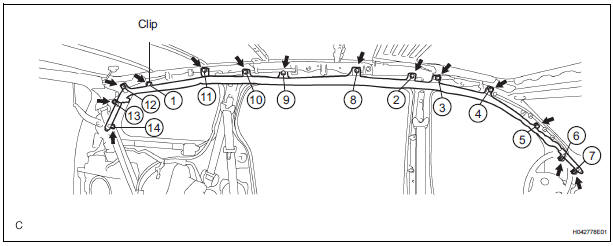
8. REMOVE CURTAIN SHIELD AIRBAG ASSEMBLY LH
- Disconnect the connector from the curtain shield
airbag assembly LH.
NOTICE: When handling the airbag connector, take care not to damage the airbag wire harness.
- Remove the clip.
- Remove the 13 bolts and the curtain shield airbag assembly LH in the order shown in the illustration.
 On-vehicle inspection
1. INSPECT CURTAIN SHIELD AIRBAG ASSEMBLY
(VEHICLE NOT INVOLVED IN COLLISION)
Perform a diagnostic system check.
With the curtain shield airbag assembly installed on
the vehic ...
 Installation
HINT:
Use the same procedures for the RH side and LH side.
The procedures listed below are for the LH side.
1. INSTALL CURTAIN SHIELD AIRBAG ASSEMBLY LH
Install the curt ...
Other materials:
ECM Communication Stop Mode
DESCRIPTION
Detection Item
Symptom
Trouble Area
ECM Communication Stop
Mode
"Engine" is not displayed on the "Communication
Bus Check" screen of the intelligent tester
Applies to "ECM Communication Stop Mode" in ...
Repair
1. REPAIR REAR WINDOW DEFOGGER WIRE
Clean the broken wire tips with grease, wax and
silicone remover.
Place the masking tape along the both sides of the
wire.
Thoroughly mix the repair agent (Dupont paste No.
4817).
Using a fine tip brush, apply a smal ...
Camshaft Position "B" Actuator Circuit / Open
DTC P0013 Camshaft Position "B" Actuator Circuit / Open
(Bank 1)
DTC P0023 Camshaft Position "B" Actuator Circuit / Open
(Bank 2)
DESCRIPTION
The Variable Valve Timing (VVT) system includes the ECM, OCV and VVT
controller. The ECM sends a
target duty-cycle control signal ...
