Toyota Sienna Service Manual: Installation
HINT:
- Use the same procedures for the RH side and LH side.
- The procedures listed below are for the LH side.
1. INSTALL CURTAIN SHIELD AIRBAG ASSEMBLY LH
- Install the curtain shield airbag assembly LH with the 13 bolts in the order shown in the illustration.
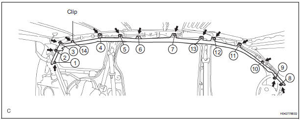
Torque: 14 N*m (143 kgf*cm, 10 ft.*lbf)
NOTICE: Do not twist the curtain shield airbag assembly LH when installing it.
- Install the clip.
- Connect the connector to the curtain shield airbag assembly LH.
NOTICE: When handling the airbag connector, take care not to damage the airbag wire harness.
2. INSTALL POWER BACK DOOR UNIT ASSEMBLY
3. INSTALL ROOF HEADLINING ASSEMBLY
HINT: Refer to the procedures from "INSTALL ROOF HEADLINING ASSEMBLY" (4).
4. INSTALL INSTRUMENT PANEL SUB-ASSEMBLY
5. INSPECT STEERING WHEEL CENTER POINT
6. INSTALL STEERING PAD
7. CONNECT CABLE TO NEGATIVE BATTERY TERMINAL
8. PERFORM INITIALIZATION
- Perform initialization.
HINT: Some systems need initialization when disconnecting the cable from the negative battery terminal.
9. INSPECT SRS WARNING LIGHT
- Inspect the SRS warning light
 Removal
HINT:
Use the same procedures for the RH side and LH side.
The procedures listed below are for the LH side.
1. PRECAUTION
CAUTION:
Be sure to read "PRECAUTION" thoroug ...
 Disposal
HINT:
Use the same procedures for the RH side and LH side.
The procedures listed below are for the LH side.
When scrapping a vehicle equipped with the SRS or
disposing of t ...
Other materials:
Steering Pad Switch Circuit
DESCRIPTION
This circuit sends an operation signal from the steering pad switch to the
radio receiver.
If there is an open in the circuit, the navigation system cannot be operated
using the steering pad switch.
If there is a short in the circuit, the resulting condition is the same as if ...
Reassembly
1. INSTALL FRONT DOOR WIRE LH
Install the wire with the 2 bolts.
Torque: Reference
8.0 N*m (82 kgf*cm, 71 in.*lbf)
NOTICE:
In order to prevent water leakage, be sure that
the lip of the rubber grommet does not turn up
or is not deformed when installing the wire.
Connect the wir ...
Fuel sender gauge
assembly
INSPECTION
1. INSPECT FUEL SENDER GAUGE ASSEMBLY
Disconnect the connector from the fuel sender
gauge.
Check that the float moves smoothly between F and
E.
Measure the resistance between terminals 1 and 2
of the connector according to the value(s) in the
table b ...
