Toyota Sienna Service Manual: Removal
1. DISCONNECT CABLE FROM NEGATIVE BATTERY TERMINAL
2. REMOVE FRONT BUMPER ASSEMBLY
- Remove the 4 screws and separate the fender liner from the front bumper assembly.
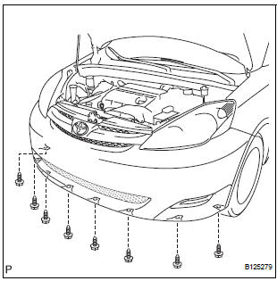
- Remove the 8 screws and separate the engine under cover from the front bumper assembly.
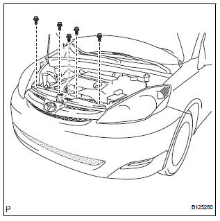
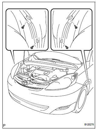
- Remove the 5 clips.
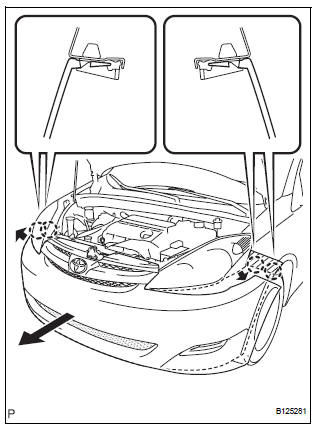
- Disengage the claws on the left and right sides of the front bumper and pull the front bumper toward the front of the vehicle as shown in the illustration.
HINT:
- Apply protective tape to the bottom part of the front fender to prevent it from being damaged.
- Disconnect the connectors if necessary.
 Front bumper
COMPONENTS
...
 Disassembly
1. REMOVE FRONT BUMPER ENERGY ABSORBER
2. REMOVE FRONT BUMPER REINFORCEMENT SUBASSEMBLY
Remove the 6 bolts and the front bumper
reinforcement sub-assembly.
3. REMOVE FRONT BUMPER SIDE SU ...
Other materials:
Speaker Circuit
DESCRIPTION
When the vehicle has a built-in type amplifier, a sound signal is
sent from the radio receiver to the
speakers via the "6 Speaker System" circuit.
When the vehicle has a separate type amplifier, a sound signal
from the radio receiver is amplified by
...
Mirror Motor Circuit
DESCRIPTION
A mirror control switch signal and memorized mirror positions are sent to the
outer mirror control ECU.
The outer mirror control ECU drives the selected mirror UP, DOWN, LEFT and RIGHT
in response to the
inputs.
HINT:
The power mirror control system is part of the large-scale ...
Speaker Circuit
DESCRIPTION
The sound signal that has been amplified by the stereo component amplifier is
sent to the speakers from
the stereo component amplifier through this circuit.
If there is a short in this circuit, the stereo component amplifier detects it
and stops output to the speakers.
Thus s ...
