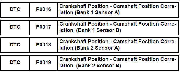
Toyota Sienna Service Manual: Crankshaft Position - Camshaft Position Correlation
DESCRIPTION
Refer to DTC P0335 (See page ES-220).
MONITOR DESCRIPTION
DTC P0016 and P0018
The ECM optimizes the valve timing by using the VVT (Variable Valve Timing) system to control the intake camshaft. The VVT system includes the ECM, the Oil Control Valve (OCV) and the VVT controller.
The ECM sends a target duty-cycle control signal to the OCV. This control signal regulates the oil pressure applied to the VVT controller. The VVT controller can advance or retard the intake camshaft. The ECM calibrates the intake valve timing by setting the intake camshaft to the most retarded angle while the engine is idling. The ECM closes the OCV to retard the cam. The ECM stores this value as the VVT learning value. When the difference between the target and actual intake valve timings is 5° CA (Crankshaft Angle) or less, the ECM stores it.
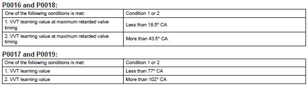
If the VVT learning value matches the following conditions, the ECM determines the existence of a malfunction in the VVT system, and sets the DTC.
- The VVT learning value: Less than 18.5° CA, or more than 43.5° CA.
- The above condition continues for 18 seconds or more.
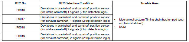
This DTC indicates that the intake camshaft has been installed toward the crankshaft at an incorrect angle, caused by factors such as the timing chain having jumped a tooth.
This monitor begins to run after the engine has idled for 5 minutes.
DTC P0017 and P0019
The ECM checks valve timing (VVT learning value) on the exhaust side while the engine is running at a low speed, in order to monitor the gap between current and target valve timings on the exhaust side. The VVT learning value is calculated from the positions of the camshaft and crankshaft. The camshaft will come to the most retarded position when the engine is running at a low speed. If the camshaft position is normal, the VVT learning value should be within the specified range. If the VVT learning value is not within the specified range, the ECM determines this as a malfunction.
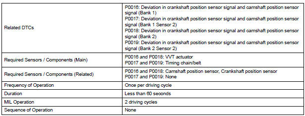
MONITOR STRATEGY
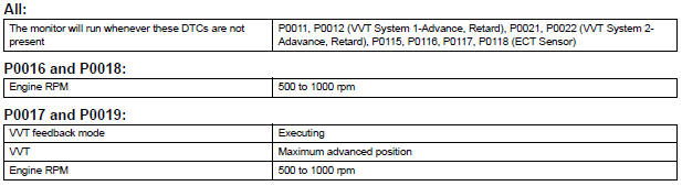
TYPICAL ENABLING CONDITIONS
TYPICAL MALFUNCTION THRESHOLDS
WIRING DIAGRAM
Refer to DTC P0335 (See page ES-222).
INSPECTION PROCEDURE
HINT:
Read freeze frame data using the intelligent tester. The ECM records vehicle and driving condition information as freeze frame data the moment a DTC is stored. When troubleshooting, freeze frame data can be helpful in determining whether the vehicle was running or stopped, whether the engine was warmed up or not, whether the air-fuel ratio was lean or rich, as well as other data recorded at the time of a malfunction.
1 CHECK VALVE TIMING (CHECK FOR LOOSE AND A JUMPED TOOTH OF TIMING CHAIN)
(a) Remove the cylinder head covers RH and LH.
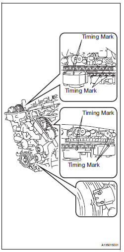
(b) Turn the crankshaft to align the matchmarks of the crankshaft.
(c) Align the notch of the crankshaft pulley to the "0" position.
(d) Check if the matchmarks of the camshaft pulley and camshaft bearing cap align.
(e) Turn the crankshaft clockwise by 360° if the matchmarks do not align. Check if they align once again.
OK: The matchmarks of the camshaft pulley and the camshaft bearing cap align when the notch of the crankshaft pulley is in the "0" position.
NOTICE:
After replacing the ECM or adjusting intake valve timing, confirm that the DTC output does not recur.
(f) Confirm that the DTC output does not recur.
(1) Connect the intelligent tester to the DLC3.
(2) Turn the ignition switch to the ON position.
(3) Turn the tester on.
(4) Clear the DTCs (See page ES-39).
(5) Select the check mode using the tester (See page ES-43).
(6) Start the engine and warm it up.
(7) Allow the engine to idle for 1 minute or more, and then drive the vehicle for 1 minute or more.
(8) Confirm that no DTC is set using the tester.

REPLACE ECM (See page ES-498)
 Camshaft Position "B" - Timing Over
HINT:
If DTC P0014, P0015, P0024 or P0025 is present, check the VVT (Variable Valve
Timing) system.
DESCRIPTION
Refer to DTC P0013 (See page ES-87).
MONITOR DESCRIPTION
DTC P0014 and P0 ...
 Oxygen (A/F) Sensor Heater Control Circuit
HINT
Although the DTC titles say the oxygen sensor, these DTCs relate to the
Air-Fuel Ratio (A/F) sensor.
Sensor 1 refers to the sensor mounted in front of the Three-Way
Catalytic Conv ...
Other materials:
Selecting the audio
source
Switching between audio sources such as radio and CD are
explained in this section.
Changing audio source
Press the “AUDIO” button to display the audio source selection
screen.
If the audio source selection screen is not displayed, press the “AUDIO”
button again.
Select the des ...
Removal
1. REMOVE NO. 1 ENGINE UNDER COVER (See page
EM-26)
2. REMOVE EXHAUST PIPE ASSEMBLY
for 2WD:(See page EX-2)
for 4WD:(See page EX-8)
3. DRAIN ENGINE COOLANT (See page CO-6)
4. DRAIN ENGINE OIL (See page LU-4)
5. REMOVE NO. 2 MANIFOLD STAY (See page EM-39)
6. REMOVE NO. 2 EXHAUST MANIFOLD HEAT ...
Turbine Speed Sensor Circuit No Signal
DESCRIPTION
This sensor detects the rotation speed of the input turbine. By comparing the
input turbine speed signal
(NT) with the counter gear speed sensor signal (NC), the ECM detects the shift
timing of the gears and
appropriately controls the engine torque and hydraulic pressure accor ...
