Toyota Sienna Service Manual: Installation
1. INSTALL TRANSMISSION CONTROL CABLE ASSEMBLY
(a) Pull in the control cable to the body.
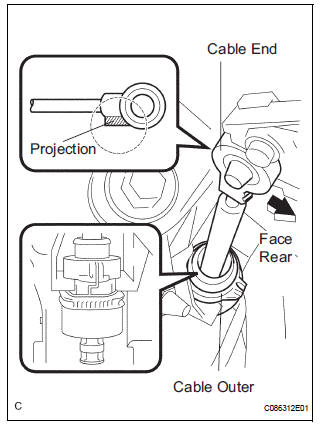
(b) Install the cable end, as shown in the illustration.
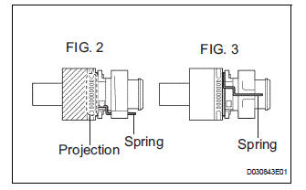
(c) When installing the transmission control cable assembly on the shift lever plate, place the projection of the shift cable downward to fit in the groove of the shift lever plate (FIG.2) Confirm that the spring in the shift cable outer has moved to the position (FIG.3) shown in the illustration.
Confirm that the shift cable is installed on the shift lever plate properly.
NOTICE:
- To prevent torsion of the inner cable, the projection on the eye end should face rear.
- Push the cable end to the bottom of the pin.
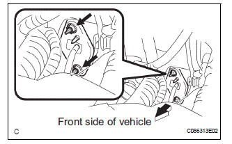
d) Install the transmission control cable assembly and 2 nuts.
Torque: 12 N*m (122 kgf*cm, 9 ft.*lbf)
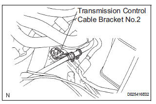
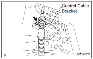
(e) Connect the transmission control cable assembly to the transmission control cable bracket No.2.
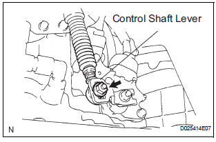
(f) Temporarily install the transmission control cable assembly to the control shaft lever with the nut.
(g) Install the transmission control cable assembly and clip to the bracket.
2. INSTALL INSTRUMENT CLUSTER FINISH PANEL SUB-ASSEMBLY CENTER
HINT: (See page IP-15)
3. ADJUST SHIFT LEVER POSITION
HINT: (See page AX-155)
4. INSPECT SHIFT LEVER POSITION
HINT: (See page AX-155)
 Adjustment
1. INSPECT SHIFT LEVER POSITION
(a) When shifting from P to R position only with ignition
switch ON and brake pedal, make sure that the
shifting lever moves smoothly and can be
moderately operated ...
Other materials:
Problem symptoms table
POWER WINDOW CONTROL SYSTEM (W/O JAM PROTECTION)
Symptom
Suspected Area
All power windows do not operate
PWR fuse
Power window relay (Marking: P/W)
Ignition switch
Power window regulator master switch
Power window regulator motor assembly
...
Disassembly
1. INSPECT PACK CLEARANCE OF FORWARD
CLUTCH
HINT:
(See page AX-242)
2. REMOVE FORWARD MULTIPLE DISC CLUTCH DISC
(a) Using a screwdriver, remove the snap ring.
(b) Remove the flange, 5 discs and 5 plates from the
input shaft assembly.
3. REMOVE FORWARD CLUTCH RETURN SPRING
SUB-ASSEMB ...
High Temperature
DTC 58-45 High Temperature
DTC 80-45 High Temperature
DESCRIPTION
DTC No.
DTC Detection Condition
Trouble Area
58-45
High map disc player temperature is detected (Over
80C).
Radio and navigation assembly
80-45
High map disc player tem ...
