
Toyota Sienna Service Manual: Removal
1. REMOVE NO. 1 ENGINE UNDER COVER (See page EM-26) 2. REMOVE EXHAUST PIPE ASSEMBLY for 2WD:(See page EX-2) for 4WD:(See page EX-8) 3. DRAIN ENGINE COOLANT (See page CO-6) 4. DRAIN ENGINE OIL (See page LU-4) 5. REMOVE NO. 2 MANIFOLD STAY (See page EM-39) 6. REMOVE NO. 2 EXHAUST MANIFOLD HEAT INSULATOR (See page EM-40) 7. REMOVE EXHAUST MANIFOLD SUB-ASSEMBLY LH (See page EM-40) 8. REMOVE ENGINE OIL COOLER
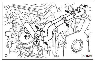
(a) Remove the bolt, 2 clamps, and 4 clips and disconnect the 2 water by-pass hoses.
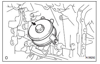
(b) Remove the oil cooler union bolt, oil cooler assembly, and O-ring.
INSPECTION
1. INSPECT ENGINE OIL COOLER
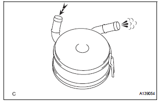
(a) Check the engine oil cooler for damage or clogging.
If necessary, replace the oil cooler.
 Engine oil cooler
Components
...
 Installation
1. INSTALL ENGINE OIL COOLER
(a) Clean the oil cooler contact surface on the cooler
mounting.
(b) Install a new O-ring to the oil cooler.
(c) Install the oil cooler assembly with the uni ...
Other materials:
Inspection
1. INSPECT NO. 1 VALVE ROCKER ARM SUBASSEMBLY
(a) Turn the roller by hand to check that it turns
smoothly.
HINT:
If the roller does not turn smoothly, replace the valve
rocker arm sub-assembly.
2. INSPECT VALVE LASH ADJUSTER ASSEMBLY
NOTICE:
Keep the lash adjuster free of dirt ...
DTC check / clear
1. CHECK DTC (USING INTELLIGENT TESTER)
Checking DTCs.
Connect the intelligent tester to the DLC3.
Turn the ignition switch ON.
Read DTCs by following the prompts on the
tester screen.
HINT:
Refer to the intelligent tester operator's manual
for further deta ...
Installation
1. Install air fuel ratio sensor (for bank 2
sensor 1)
(a) Using SST, install the sensor to the exhaust
manifold LH.
SST 09224-00010
Torque: 40 N*m (408 kgf*cm, 30 ft.*lbf) for use
with SST
44 N*m (449 kgf*cm, 32 ft.*lbf) for use
without SST
HINT:
Use a torque wrench with a fulcrum ...
