Toyota Sienna Service Manual: Installation
1. INSTALL ENGINE OIL COOLER
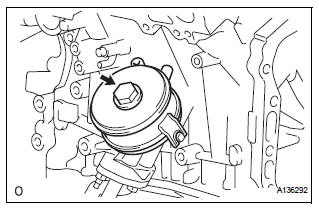
(a) Clean the oil cooler contact surface on the cooler mounting.
(b) Install a new O-ring to the oil cooler.
(c) Install the oil cooler assembly with the union bolt.
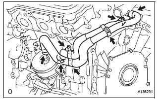
Torque: 68 N*m (693 kgf*cm, 50 ft.*lbf) Install the 2 water by-pass hoses with the bolt, 2 clamps, and 4 clips.
Torque: 10 N*m (102 kgf*cm, 7 ft.*lbf)
2. INSTALL EXHAUST MANIFOLD SUB-ASSEMBLY LH (See page EM-47) 3. INSTALL NO. 2 EXHAUST MANIFOLD HEAT INSULATOR (See page EM-48) 4. INSTALL NO. 2 MANIFOLD STAY (See page EM-48) 5. INSTALL EXHAUST PIPE ASSEMBLY
for 2WD:(See page EX-4) for 4WD:(See page EX-10)
6. ADD ENGINE OIL (See page LU-6)
7. ADD ENGINE COOLANT (See page CO-7)
8. INSPECT FOR OIL LEAK (See page LU-6)
9. CHECK ENGINE OIL LEVEL
10. INSTALL NO. 1 ENGINE UNDER COVER (See page EM-63)
 Removal
1. REMOVE NO. 1 ENGINE UNDER COVER (See page
EM-26)
2. REMOVE EXHAUST PIPE ASSEMBLY
for 2WD:(See page EX-2)
for 4WD:(See page EX-8)
3. DRAIN ENGINE COOLANT (See page CO-6)
4. DRAIN ENGINE OIL (S ...
 Engine
...
Other materials:
Brake System Malfunction
DTC P1578 Brake System Malfunction
DESCRIPTION
This DTC is output when the VSC system has a problem. Check the VSC system
when this DTC is
output
DTC No.
DTC Detection Condition
Trouble Area
P1578
The ECM receives a brake system error signal for 0.2
...
Airbag ECU Communication Stop
DTC B1281 Airbag ECU Communication Stop
DESCRIPTION
DTC B1281 is output when communication between the airbag ECU and the
multiplex network gateway
ECU stops for more than 10 seconds.
DTC No.
DTC Detection Condition
Trouble Area
B1281
Airbag ECU communi ...
Input instructions
(a) The general VIN input instructions using the
intelligent tester are shown below:
(b) The arrow buttons (UP, DOWN, RIGHT and LEFT)
and numerical buttons (0 to 9) are used to input the
VIN.
(c) Cursor Operation
To move the cursor around the tester screen, press
the RIGHT and LEFT buttons. ...
