Toyota Sienna Service Manual: Shift lock system
On-vehicle inspection
1. CHECK SHIFT LOCK OPERATION
(a) Move the shift lever to the P position.
(b) Turn the ignition switch to the LOCK position.
(c) Check that the shift lever cannot be moved to any position other than P.
(d) Turn the ignition switch to the on position, depress the brake pedal and check that the shift lever can be moved to another position. If operation can not be done as specified, inspect the shift lock control unit.
2. CHECK SHIFT LOCK RELEASE BUTTON OPERATION
(a) Using a small screwdriver, remove the shift lock release cover.
(b) When operating the shift lever with the shift lock release button pressed, check that the lever can be moved to any position other than P.
If operation can not be done as specified, check the shift lever assembly installation condition.
3. CHECK KEY INTERLOCK OPERATION
(a) Turn the ignition switch to the ON position.
(b) Depress the brake pedal and move the shift lever to any position other than P.
(c) Check that the ignition key cannot be turned to the LOCK position.
(d) Move the shift lever to the P position, turn the ignition key to the LOCK position and check that the ignition key can be removed.
If operation cannot be done as specified, inspect the shift lock control unit.
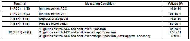
4. INSPECT SHIFT LOCK CONTROL UNIT ASSEMBLY
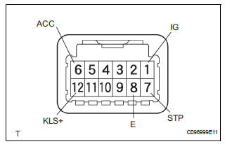
(a) Measure the voltage according to the value(s) in the table below.
HINT: Do not disconnect the shift lock control unit assembly connector.
Voltage

(b) Measure the resistance according to the value(s) in the table below.
HINT: Do not disconnect the shift lock control unit assembly connector.
If operation cannot be done as specified, replace the shift lever assembly.
Resistance

5. INSPECT KEY INTER LOCK SOLENOID
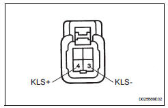
(a) Disconnect the solenoid connector.
(b) Connect KLS+ (4) terminal to the batteries' positive (+) terminal and KLS (3) terminal to the battery negative (-) terminal, and apply about 12 V between KLS+ - KLS- terminals.
(c) Check that operation noise can be heard from the solenoid.
If the solenoid does not operate, replace the solenoid.
6. INSPECT SHIFT LOCK SOLENOID
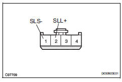
(a) Disconnect the solenoid connector.
(b) Connect SSL+ (2) terminal to the batteries' positive (+) terminal, and SLS- (1) terminal to the battery negative (-) terminal, and apply about 12 V between SLL+-SLS- terminals.
(c) Check that operation noise can be heard from the solenoid.
If the solenoid does not operate, replace the solenoid.
 Installation
1. Install transmission valve body assembly
(a) Install the shift solenoid valve SL1 to the valve body
assembly with the bolt.
Torque: 6.6 N*m (67 kgf*cm, 58 in.*lbf)
(b) Install the shi ...
 Shift lever
Components
...
Other materials:
Fuel Receiver Gauge Malfunction
DESCRIPTION
The meter CPU uses the fuel sender gauge assembly to determine the level of
the fuel in the fuel tank.
The resistance of the fuel sender gauge will vary between approximately 15 Ω
with the float at the full
position, and 410 Ω with the float at the empty position. The ...
Reassembly
1. INSTALL GENERATOR ROTOR ASSEMBLY
(a) Place the drive end frame on the clutch pulley.
(b) Install the generator rotor assembly to the drive end
frame.
(c) Place a new generator washer on the generator
rotor.
2. INSTALL GENERATOR COIL ASSEMBLY
(a) Using a deep socket wrench (21 ...
Armrests
Pull the armrest down for use.
Front seat
Second seat (if equipped)
Adjusting the front seat armrests (if equipped)
Push the armrest down while pressing the
button.
NOTICE
To prevent damage to the armrest, do not apply too much load on the
armrest.
...
