Toyota Sienna Service Manual: Installation
1. Install transmission valve body assembly
(a) Install the shift solenoid valve SL1 to the valve body assembly with the bolt.
Torque: 6.6 N*m (67 kgf*cm, 58 in.*lbf)
(b) Install the shift solenoid valve SL2 to the valve body assembly with the bolt.
Torque: 11 N*m (110 kgf*cm, 8 ft.*lbf)
(c) Install the shift solenoid valve DSL to the valve body assembly with the bolt.
Torque: 11 N*m (110 kgf*cm, 8 ft.*lbf)
(d) Install the shift solenoid valve SR to the valve body assembly.
(e) Install the shift solenoid valve S4 to the valve body assembly with the bolt.
Torque: 11 N*m (110 kgf*cm, 8 ft.*lbf)
(f) Install the shift solenoid valve SL3 and SLT to the valve body assembly.
(g) Install the lock plate to the valve body assembly with the bolt.
Torque: 6.6 N*m (67 kgf*cm, 58 in.*lbf)
(h) Install the spring and check ball body.
(i) Align the groove of the manual valve with the pin of the lever.
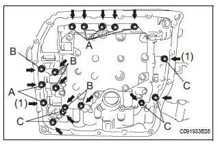
(j) Install the 17 bolts.
Torque: 11 N*m (110 kgf*cm, 8 ft.*lbf)
(i) Align the groove of the manual valve with the pin of the lever.
(j) Install the 17 bolts.
Torque: 11 N*m (110 kgf*cm, 8 ft.*lbf)
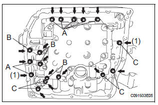
NOTICE:
|
Bolt length: Bolt A: 41 mm (1.614 in.) Bolt B: 57 mm (2.244 in.) Bolt C: 25 mm (0.984 in.)
2. INSTALL VALVE BODY OIL STRAINER ASSEMBLY
(a) Coat a new O-ring with ATF.
(b) Install the O-ring to the oil strainer.
(c) Install the oil strainer with the 3 bolts.
Torque: 11 N*m (110 kgf*cm, 8 ft.*lbf)
3. INSTALL TRANSMISSION WIRE
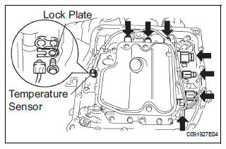
(a) Coat the O-ring with ATF.
(b) Install the ATF temperature sensor with the lock plate and bolt.
Torque: 6.6 N*m (67 kgf*cm, 58 in.*lbf) (c) Connect the 7 shift solenoid valve connectors.
4. INSTALL AUTOMATIC TRANSAXLE OIL PAN SUBASSEMBLY
(a) Install the 2 magnets in the oil pan.
(b) Apply seal packing or equivalent to the 18 bolts.
Seal packing: THREE BOND 2430 or equivalent
(c) Install the oil pan and new gasket with the 18 bolts to the transaxle case.
Torque: 7.8 N*m (80 kgf*cm, 69 in.*lbf)
| NOTICE: Tighten the bolts within 10 minutes of sealant application. |
5. CONNECT CABLE TO NEGATIVE BATTERY TERMINAL 6. ADD AUTOMATIC TRANSAXLE FLUID 7. CHECK FLUID LEVEL IN AUTOMATIC TRANSAXLE (See page AX-123) 8. INSTALL ENGINE UNDER COVER NO.1 9. RESET MEMORY
HINT: (See page AX-16)
 Removal
1. Remove engine under cover no.1
2. Disconnect cable from negative battery
terminal
3. Drain automatic transaxle fluid (see page
ax-131)
4. Remove automatic transaxle oil pan subassembly
(a ...
 Shift lock system
On-vehicle inspection
1. CHECK SHIFT LOCK OPERATION
(a) Move the shift lever to the P position.
(b) Turn the ignition switch to the LOCK position.
(c) Check that the shift lever cannot be move ...
Other materials:
Television Display Power Source Circuit
DESCRIPTION
This is the power source circuit to operate the television display assembly.
WIRING DIAGRAM
INSPECTION PROCEDURE
1 INSPECT TELEVISION DISPLAY ASSEMBLY
Disconnect the connector from the television display
assembly.
Measure the resistance according to the value(s) ...
Reassembly
1. INSTALL BRAKE PEDAL PAD
(a) Install the brake pedal pad to the brake pedal subassembly.
2. INSTALL PUSH ROD PIN
(a) Apply lithium soap base glycol grease to inside
surface of 2 new push rod bushes.
(b) Install the 2 new push rod bushes.
(c) Install the 2 push rod pins with the 2 plate t ...
Disassembly
1. REMOVE REAR DOOR WINDOW FRAME MOULDING
REAR LH (See page ET-31)
2. REMOVE REAR DOOR WINDOW FRAME MOULDING
SUB-ASSEMBLY LH (See page ET-32)
3. REMOVE SLIDE DOOR WINDOW GARNISH LH
Fully open the slide door window.
Remove the glass run.
Using a screwdriver, disengage the clip and rem ...
