Toyota Sienna Service Manual: Short to B+ in Curtain Shield Squib LH Circuit
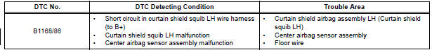
DTC B1168/86 Short to B+ in Curtain Shield Squib LH Circuit
DESCRIPTION
The curtain shield squib LH circuit consists of the center airbag sensor assembly and the curtain shield airbag assembly LH.
The circuit instructs the SRS to deploy when deployment conditions are met.
DTC B1168/86 is recorded when a short to B+ is detected in the curtain shield squib LH circuit.
WIRING DIAGRAM
INSPECTION PROCEDURE
HINT:
- Perform the simulation method by selecting the "check mode" (signal check) with the intelligent tester.
- After selecting the "check mode" (signal check), perform the simulation method by wiggling each connector of the airbag system or driving the vehicle on a city or rough road
1 CHECK CURTAIN SHIELD AIRBAG ASSEMBLY LH (CURTAIN SHIELD SQUIB LH)
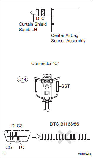
- Turn the ignition switch to the LOCK position.
- Disconnect the negative (-) terminal cable from the battery, and wait for at least 90 seconds.
- Disconnect the connectors from the curtain shield airbag assembly LH.
- Connect the white wire side of SST (resistance 2.1 Ω) to
the floor wire.
CAUTION: Never connect a tester to the curtain shield airbag assembly LH (curtain shield squib LH) for measurement, as this may lead to a serious injury due to airbag deployment.
NOTICE: Do not forcibly insert the SST into the terminals of the connector when connecting.
Insert the SST straight into the terminals of the connector.
SST 09843-18060
- Connect the negative (-) terminal cable to the battery, and wait for at least 2 seconds.
- Turn the ignition switch to the ON position, and wait for at least 60 seconds.
- Clear the DTCs stored in memory.
- Turn the ignition switch to the LOCK position.
- Turn the ignition switch to the ON position, and wait for at least 60 seconds.
- Check the DTCs
OK: DTC B1168/86 is not output.
HINT: Codes other than DTC B1168/86 may be output at this time, but they are not related to this check.
REPLACE CURTAIN SHIELD AIRBAG ASSEMBLY LH
2 CHECK FLOOR WIRE (CURTAIN SHIELD SQUIB LH CIRCUIT)
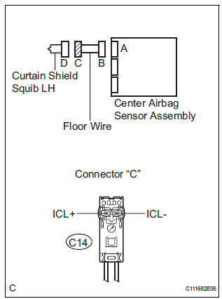
- Turn the ignition switch to the LOCK position.
- Disconnect the negative (-) terminal cable from the battery, and wait for at least 90 seconds.
- Disconnect the SST (resistance 2.1 Ω) from the floor wire.
- Disconnect the connector from the center airbag sensor assembly.
- Connect the negative (-) terminal cable to the battery, and wait for at least 2 seconds.
- Turn the ignition switch to the ON position.
- Measure the voltage according to the value(s) in the table below.
Standard voltage

3 CHECK CENTER AIRBAG SENSOR ASSEMBLY

- Turn the ignition switch to the LOCK position.
- Disconnect the negative (-) terminal cable from the battery, and wait for at least 90 seconds.
- Connect the connectors to the curtain shield airbag assembly LH and the center airbag sensor assembly.
- Connect the negative (-) terminal cable to the battery, and wait for at least 2 seconds.
- Turn the ignition switch to the ON position, and wait for at least 60 seconds.
- Clear the DTCs stored in memory.
- Turn the ignition switch to the LOCK position.
- Turn the ignition switch to the ON position, and wait for at least 60 seconds.
- Check the DTCs.
OK: DTC B1168/86 is not output.
HINT: Codes other than code B1168/86 may be output at this time, but they are not related to this check.
USE SIMULATION METHOD TO CHECK
 Short to GND in Curtain Shield Squib LH Circuit
DTC B1167/85 Short to GND in Curtain Shield Squib LH Circuit
DESCRIPTION
The curtain shield squib LH circuit consists of the center airbag sensor
assembly and the curtain shield
airbag assembly L ...
 Short in Driver Side Squib 2nd Step Circuit
DTC B1180/17 Short in Driver Side Squib 2nd Step Circuit
DESCRIPTION
The driver side squib 2nd step circuit consists of the center airbag sensor
assembly, the spiral cable and
the steering pad.
...
Other materials:
Open in Driver Side Squib 2nd Step Circuit
DTC B1181/18 Open in Driver Side Squib 2nd Step Circuit
DESCRIPTION
The driver side squib 2nd step circuit consists of the center airbag sensor
assembly, the spiral cable and
the steering pad.
The circuit instructs the SRS to deploy when deployment conditions are met.
DTC B1181/18 is reco ...
Problem symptoms table
RESULT LIST OF CHECK CAN BUS LINE
Symptom
Suspected Area
All ECUs and sensors connected to the CAN
communication system are not displayed on intelligent
tester
CAN Bus Line
The result of "CAN BUS WIRE CHECK" is "Open in
CAN Main Bus Lin ...
Fastening the seat belt (for the third center seat)
Take the plate out of the holder,
and then pull down the seat
belt.
Push plate “A” into buckle “A”
until a click sound is heard.
Push plate “B” into buckle “B”
until a click sound is heard.
...
