Toyota Sienna Service Manual: Short in Driver Side Squib 2nd Step Circuit
DTC B1180/17 Short in Driver Side Squib 2nd Step Circuit
DESCRIPTION
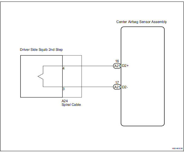
The driver side squib 2nd step circuit consists of the center airbag sensor assembly, the spiral cable and the steering pad.
The circuit instructs the SRS to deploy when deployment conditions are met.
DTC B1180/17 is recorded when a short circuit is detected in the driver side squib 2nd step circuit
WIRING DIAGRAM
INSPECTION PROCEDURE
HINT:
- Perform the simulation method by selecting the "check mode" (signal check) with the intelligent tester
- After selecting the "check mode" (signal check), perform the simulation method by wiggling each connector of the airbag system or driving the vehicle on a city or rough road
1 CHECK STEERING PAD (DRIVER SIDE SQUIB 2ND STEP)
- Turn the ignition switch to the LOCK position.
- Disconnect the negative (-) terminal cable from the battery, and wait for at least 90 seconds.
- Disconnect the connectors from the steering pad.
- Connect the white wire side of SST (resistance 2.1 Ω) to
the spiral cable.
CAUTION: Never connect a tester to the steering pad (driver side squib 2nd step) for measurement, as this may lead to a serious injury due to airbag deployment.
NOTICE: Do not forcibly insert the SST into the terminals of the connector when connecting.
Insert the SST straight into the terminals of the connector.
SST 09843-18060
- Connect the negative (-) terminal cable to the battery, and wait for at least 2 seconds.
- Turn the ignition switch to the ON position, and wait for at least 60 seconds.
- Clear the DTCs stored in memory.
- Turn the ignition switch to the LOCK position.
- Turn the ignition switch to the ON position, and wait for at least 60 seconds.
- Check the DTCs.
OK: DTC B1180/17 is not output.
HINT: Codes other than DTC B1180/17 may be output at this time, but they are not related to this check.
REPLACE STEERING PAD
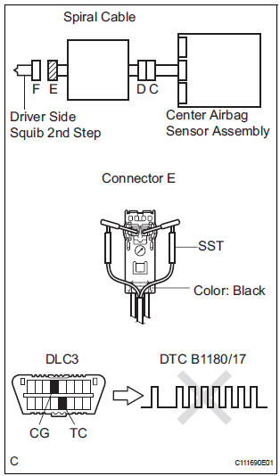
2 CHECK CONNECTORS
- Turn the ignition switch to the LOCK position.
- Disconnect the negative (-) terminal cable from the battery, and wait for at least 90 seconds.
- Disconnect the SST (resistance 2.1 Ω) from the spiral cable.
- Check that the spiral cable connectors (on the steering pad side) are not damaged.
OK: The lock button is not disengaged, and the claw of the lock is not deformed or damaged.
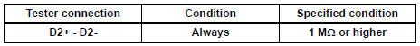
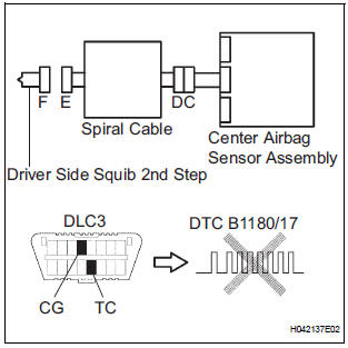
3 CHECK DRIVER SIDE SQUIB 2ND STEP CIRCUIT
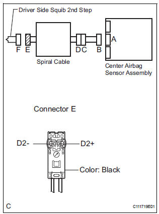
- Disconnect the connector from the center airbag sensor assembly.
- Release the activation prevention mechanism built into connector "B".
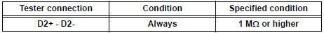
- Measure the resistance according to the value(s) in the table below.
Standard resistance
4 CHECK CENTER AIRBAG SENSOR ASSEMBLY
- Connect the connectors to the steering pad and the center airbag sensor assembly.
- Connect the negative (-) terminal cable to the battery, and wait for at least 2 seconds.
- Turn the ignition switch to the ON position, and wait for at least 60 seconds.
- Clear the DTCs stored in memory.
- Turn the ignition switch to the LOCK position.
- Turn the ignition switch to the ON position, and wait for at least 60 seconds.
- Check the DTCs.
OK: DTC B1180/17 is not output.
HINT: Codes other than DTC B1180/17 may be output at this time, but they are not related to this check.
USE SIMULATION METHOD TO CHECK
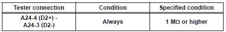
5 CHECK INSTRUMENT PANEL WIRE
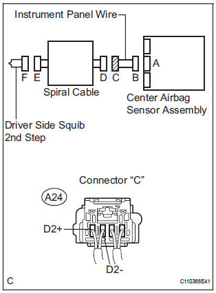
- Disconnect the instrument panel wire connector from the
spiral cable.
HINT: The activation prevention mechanism of connector "B" has already been released.
- Measure the resistance according to the value(s) in the table below.
Standard resistance
6 CHECK SPIRAL CABLE

- Release the activation prevention mechanism built into connector "D".
- Measure the resistance according to the value(s) in the table below.
Standard resistance
USE SIMULATION METHOD TO CHECK
 Short to B+ in Curtain Shield Squib LH Circuit
DTC B1168/86 Short to B+ in Curtain Shield Squib LH Circuit
DESCRIPTION
The curtain shield squib LH circuit consists of the center airbag sensor
assembly and the curtain shield
airbag assembly LH ...
 Open in Driver Side Squib 2nd Step Circuit
DTC B1181/18 Open in Driver Side Squib 2nd Step Circuit
DESCRIPTION
The driver side squib 2nd step circuit consists of the center airbag sensor
assembly, the spiral cable and
the steering pad.
...
Other materials:
Installation
1. INSTALL AIR CONDITIONING BLOWER ASSEMBLY
(a) Install the air conditioning blower assembly with the
3 bolts.
Torque: 5.4 N*m (55 kgf*cm, 48 in.*lbf)
NOTICE:
Tighten the bolts in the order shown in the
illustration to install the air conditioning blower
assembly.
2. INSTALL AIR CONDITIO ...
Inspection
1. Inspect heated oxygen sensor (for bank 1
sensor 2)
(a) Measure the resistance of the sensor.
Standard resistance
If the resistance is not as specified, replace the
sensor.
2. HEATED OXYGEN SENSOR (for Bank 2 Sensor 2)
(a) Measure the resistance of the sensor.
Standard resistance ...
ECU Power Source Circuit
DESCRIPTION
This is the power source for the tire pressure warning ECU.
WIRING DIAGRAM
INSPECTION PROCEDURE
NOTICE:
When replacing the tire pressure warning ECU, read the transmitter IDs
stored in the old ECU
using the intelligent tester and write them down before removal.
It is neces ...
