
Toyota Sienna Service Manual: Short to B+ in Front Pretensioner Squib RH Circuit
DTC B0133/62 Short to B+ in Front Pretensioner Squib RH Circuit
DESCRIPTION
The front pretensioner squib RH circuit consists of the center airbag sensor assembly and the front seat outer belt assembly RH.
This circuit instructs the SRS to deploy when deployment conditions are met.
DTC B0133/62 is recorded when a short to B+ is detected in the front pretensioner squib RH circuit.
|
DTC No. |
DTC Detecting Condition |
Trouble Area |
| B0133/62 |
|
|
INSPECTION PROCEDURE
HINT:
- Perform the simulation method by selecting the "check mode" (signal check) with the intelligent tester (8).
- After selecting the "check mode" (signal check), perform the simulation method by wiggling each connector of the airbag system or driving the vehicle on a city or rough road
1 CHECK FRONT SEAT OUTER BELT ASSEMBLY RH (FRONT PRETENSIONER SQUIB RH)
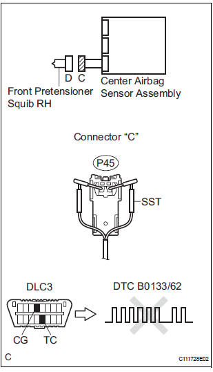
- Turn the ignition switch to the LOCK position.
- Disconnect the negative (-) terminal cable from the battery, and wait for at least 90 seconds.
- Disconnect the connectors from the front seat outer belt assembly RH.
- Connect the white wire side of SST (resistance 2.1 Ω) to the floor wire No. 2.
CAUTION: Never connect a tester to the front seat outer belt assembly RH (front pretensioner squib RH) for measurement, as this may lead to a serious injury due to airbag deployment.
NOTICE: Do not forcibly insert the SST into the terminals of the connector when connecting.
Insert the SST straight into the terminals of the connector.
SST 09843-18060
- Connect the negative (-) terminal cable to the battery, and wait for at least 2 seconds.
- Turn the ignition switch to the ON position, and wait for at least 60 seconds.
- Clear the DTCs stored in memory (5).
- Turn the ignition switch to the LOCK position.
- Turn the ignition switch to the ON position, and wait for at least 60 seconds.
- Check the DTCs (5).
OK: DTC B0133/62 is not output. HINT: Codes other than DTC B0133/62 may be output at this time, but they are not related to this check.
 Go to step 2

REPLACE FRONT SEAT OUTER BELT ASSEMBLY RH
2 CHECK FLOOR WIRE NO.2 (FRONT PRETENSIONER SQUIB RH CIRCUIT)
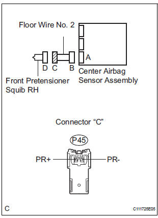
- Disconnect the connector from the center airbag sensor assembly.
- Connect the negative (-) terminal cable to the battery, and wait for at least 2 seconds.
- Turn the ignition switch to the ON position.
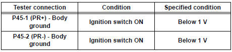
- Measure the voltage according to the value(s) in the table below.
Standard voltage
 REPAIR OR REPLACE FLOOR WIRE
NO.2
REPAIR OR REPLACE FLOOR WIRE
NO.2

3 CHECK CENTER AIRBAG SENSOR ASSEMBLY
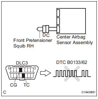
- Turn the ignition switch to the LOCK position.
- Disconnect the negative (-) terminal cable from the battery, and wait for at least 90 seconds.
- Connect the connectors to the front seat outer belt assembly RH and the center airbag sensor assembly.
- Connect the negative (-) terminal cable to the battery, and wait for at least 2 seconds.
- Turn the ignition switch to the ON position, and wait for at least 60 seconds.
- Clear the DTCs stored in memory (5).
- Turn the ignition switch to the LOCK position.
- Turn the ignition switch to the ON position, and wait for at least 60 seconds.
- Check the DTCs (5).
OK: DTC B0133/62 is not output. HINT: Codes other than code B0133/62 may be output at this time, but they are not related to this check.
 REPLACE CENTER AIRBAG SENSOR
ASSEMBLY
REPLACE CENTER AIRBAG SENSOR
ASSEMBLY
USE SIMULATION METHOD TO CHECK
 Short to GND in Front Pretensioner Squib RH
Circuit
Short to GND in Front Pretensioner Squib RH
Circuit
DTC B0132/61 Short to GND in Front Pretensioner Squib RH
Circuit
DESCRIPTION
The front pretensioner squib RH circuit consists of the center airbag sensor
assembly and the front seat
outer belt a ...
 Short in Front Pretensioner Squib LH Circuit
DTC B0135/73 Short in Front Pretensioner Squib LH Circuit
DESCRIPTION
The front pretensioner squib LH circuit consists of the center airbag sensor
assembly and the front seat
outer belt assembly ...
Other materials:
Inspection
1. Inspect generator clutch pulley
(a) Hold the center of the pulley, and confirm that the
outer ring turns counterclockwise and does not turn
clockwise.
If the result is not as specified, replace the clutch
pulley.
2. Remove generator drive end frame bearing
(a) Check that the bear ...
Disassembly
1. REMOVE RADIATOR WATER INLET
(a) Remove the 2 bolts and radiator water inlet.
2. REMOVE DRAIN PLUG
(a) Remove the drain plug and air drain plug.
(b) Remove the 2 O-rings.
3. REMOVE LOWER RADIATOR TANK
(a) Install the claw to the overhaul handle, inserting it in
the hole in Part A ...
Problem symptoms table
SLIDE DOOR CLOSER SYSTEM
Symptom
Suspected Area
Slide door closer LH does not operate (*1)
ECU-B fuse
Power slide door lock assembly LH
Power slide door ECU LH
Wire harness
Slide door closer RH does not operate
ECU-B ...
