Toyota Sienna Service Manual: Disassembly
1. REMOVE RADIATOR WATER INLET
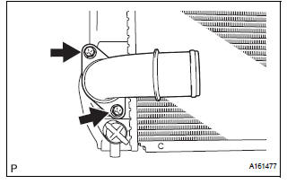
(a) Remove the 2 bolts and radiator water inlet.
2. REMOVE DRAIN PLUG
(a) Remove the drain plug and air drain plug.
(b) Remove the 2 O-rings.
3. REMOVE LOWER RADIATOR TANK
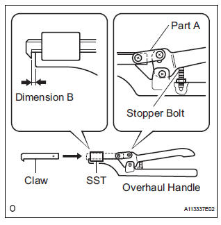
(a) Install the claw to the overhaul handle, inserting it in the hole in Part A as shown in the illustration.
SST 09230-01010 (09231-01010, 09231-01030) (b) While squeezing the handle, adjust the stopper bolt so that dimension B is as specified below.
Dimension B: 0.2 to 0.3 mm (0.008 to 0.012 in.)
| NOTICE: If the stopper bolt is not adjusted, the claw may be damaged. |
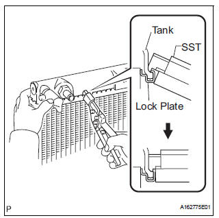
(c) Using SST, uncrimp the lock plate by squeezing the handle until stopped by the stopper bolt.
SST 09230-01010
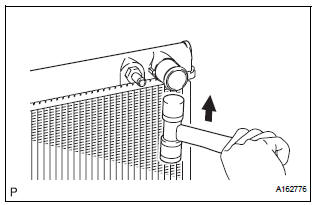
(d) Lightly tap the bracket of the radiator (or radiator hose inlet or outlet) with a soft-faced hammer and remove the tank.
(e) Remove the O-ring.
4. REMOVE UPPER RADIATOR TANK
HINT: The removal procedure for the upper radiator tank is the same as that for the lower radiator tank.
 Removal
1. REMOVE V-BANK COVER SUB-ASSEMBLY (See
page EM-28)
2. REMOVE NO. 1 ENGINE UNDER COVER (See page
EM-26)
3. DRAIN ENGINE COOLANT (See page CO-6)
4. REMOVE NO. 2 AIR CLEANER INLET (See page EM-
2 ...
 Inspection
1. INSPECT LOCK PLATE FOR DAMAGE
(a) Inspect the lock plate for damage.
HINT:
Reassembly of a deformed tank will be
impossible. Therefore, first correct the shape of
the lock plate groov ...
Other materials:
Short to GND in Front Passenger Side Squib
Circuit
DTC B0107/51 Short to GND in Front Passenger Side Squib
Circuit
DESCRIPTION
The front passenger side squib circuit consists of the center airbag sensor
assembly and the front
passenger airbag assembly.
The circuit instructs the SRS to deploy when deployment conditions are met.
DTC B0107/ ...
Basic inspection
When a malfunction is not confirmed by the DTC check,
troubleshooting should be carried out in all circuits
considered to be possible causes of the problem. In many
cases, by carrying out the basic engine check shown in the
following flowchart, the location of the problem can be found
quickly a ...
Customize parameters
HINT:
The following items can be customized.
NOTICE:
After confirming whether the items requested by the
customer are applicable or not for customization,
perform customize operations.
Be sure to record the current settings before
customizing.
When troubleshooting, ...
