Toyota Sienna Service Manual: Inspection
1. Inspect generator clutch pulley
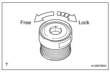
(a) Hold the center of the pulley, and confirm that the outer ring turns counterclockwise and does not turn clockwise.
If the result is not as specified, replace the clutch pulley.
2. Remove generator drive end frame bearing
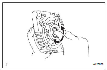
(a) Check that the bearing is not rough or worn.V
Ok: the bearing rotates smoothly.
If the bearing does not rotate smoothly, replace the bearing.
3. Inspect generator brush holder assembly
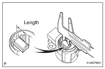
(a) Using vernier calipers, measure the length of the exposed brushes.
Standard exposed length: 9.5 to 11.5 mm (0.374 to 0.453 in.) Minimum exposed length: 4.5 mm (0.177 in.) If the exposed length is less than the minimum, replace the brush holder assembly.
4. INSPECT GENERATOR ROTOR ASSEMBLY
(a) Check that the generator rotor bearing is not rough or worn.
If necessary, replace the generator rotor assembly.
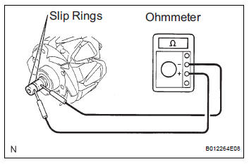
(b) Check the generator rotor for an open circuit.
(1) Using an ohmmeter, measure the resistance between the slip rings.
Standard resistance
If the result is not as specified, replace the generator rotor assembly.
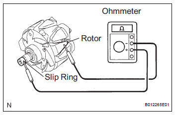
(c) Check the rotor for a short to ground.
(1) Using an ohmmeter, measure the resistance between the slip ring and rotor.
Standard resistance 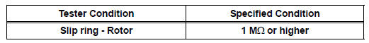
If the result is not as specified, replace the generator rotor assembly.
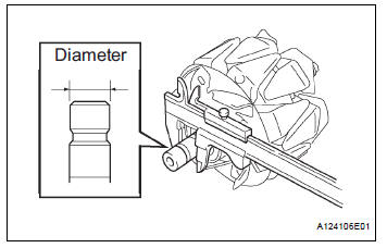
(d) Using vernier calipers, measure the slip ring diameter.
Standard diameter: 14.2 to 14.4 mm (0.559 to 0.567 in.) Minimum diameter: 14.0 mm (0.551 in.)
If the diameter is less than the minimum, replace the generator rotor assembly.
 Disassembly
1. REMOVE GENERATOR CLUTCH PULLEY
(A) using a screwdriver, remove the generator pulley
cap.
(b) Set SST (A) and (B).
SST 09820-63020
(c) Clamp SST (A) in a vise.
NOTICE:
...
 Replacement
1. REPLACE GENERATOR DRIVE END FRAME BEARING
(a) Remove the 4 screws and retainer plate from the
drive end frame.
(b) Using SST and a hammer, tap out the drive end
frame bearing from the d ...
Other materials:
Removal
HINT:
Replace the RH side using the same procedures as for the
LH side.
1. REMOVE FRONT WHEEL
2. REMOVE FRONT AXLE HUB LH NUT (See page DS-
5)
3. SEPARATE SPEED SENSOR FRONT LH (See page
DS-5)
4. SEPARATE FRONT DISC BRAKE CALIPER ASSEMBLY LH
(a) Remove the 2 bolts and separate the front ...
Quarter windows
The quarter windows can be opened to bring in fresh outside air
for additional ventilation.
Opening and closing procedures
Manual type
Pull the handle and swing the window
fully out to open.
Power type
Opening
Closing
Both the left and right quarter windows
move.
T ...
Installation
1. INSTALL NO.1 NAVIGATION BRACKET
Install the No.1 navigation bracket with the 4
screws.
2. INSTALL NO.2 NAVIGATION BRACKET
Install the No.2 navigation bracket with the 4
screws.
3. INSTALL INSTRUMENT CLUSTER FINISH PANEL UPPER
Install the instrum ...
