Toyota Sienna Service Manual: Short to GND in Driver Side Squib 2nd Step Circuit
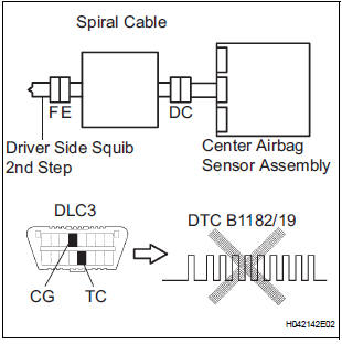
DTC B1182/19 Short to GND in Driver Side Squib 2nd Step Circuit
DESCRIPTION
The driver side squib 2nd step circuit consists of the center airbag sensor assembly, the spiral cable and the steering pad.
The circuit instructs the SRS to deploy when deployment conditions are met.
DTC B1182/19 is recorded when a short to ground is detected in the driver side squib 2nd step circuit.
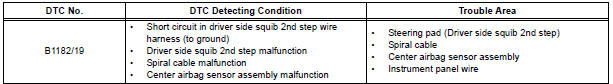
WIRING DIAGRAM
INSPECTION PROCEDURE
HINT:
- Perform the simulation method by selecting the "check mode" (signal check) with the intelligent tester.
- After selecting the "check mode" (signal check), perform the simulation method by wiggling each connector of the airbag system or driving the vehicle on a city or rough road
1 CHECK STEERING PAD (DRIVER SIDE SQUIB 2ND STEP)
- Turn the ignition switch to the LOCK position.
- Disconnect the negative (-) terminal cable from the battery, and wait for at least 90 seconds.
- Disconnect the connectors from the steering pad.
- Connect the white wire side of SST (resistance 2.1 Ω) to
the spiral cable.
CAUTION: Never connect a tester to the steering pad (driver side squib 2nd step) for measurement, as this may lead to a serious injury due to airbag deployment.
NOTICE: Do not forcibly insert the SST into the terminals of the connector when connecting.
Insert the SST straight into the terminals of the connector.
SST 09843-18060
- Connect the negative (-) terminal cable to the battery, and wait for at least 2 seconds.
- Turn the ignition switch to the ON position, and wait for at least 60 seconds.
- Clear the DTCs stored in memory.
- Turn the ignition switch to the LOCK position.
- Turn the ignition switch to the ON position, and wait for at least 60 seconds.
- Check the DTCs.
OK: DTC B1182/19 is not output.
HINT: Codes other than DTC B1182/19 may be output at this time, but they are not related to this check.
REPLACE STEERING PAD
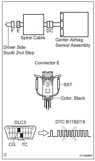
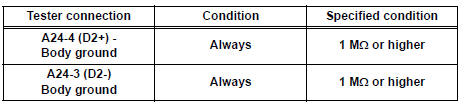
2 CHECK DRIVER SIDE SQUIB 2ND STEP CIRCUIT
- Turn the ignition switch to the LOCK position.
- Disconnect the negative (-) terminal cable from the battery, and wait for at least 90 seconds.
- Disconnect the SST (resistance 2.1 Ω) from the spiral cable.
- Disconnect the connector from the center airbag sensor assembly.
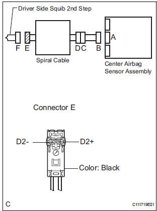
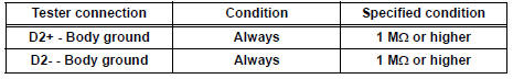
- Measure the resistance according to the value(s) in the table below.
Standard resistance
3 CHECK CENTER AIRBAG SENSOR ASSEMBLY
- Connect the connectors to the steering pad and the center airbag sensor assembly.
- Connect the negative (-) terminal cable to the battery, and wait for at least 2 seconds.
- Turn the ignition switch to the ON position, and wait for at least 60 seconds.
- Clear the DTCs stored in memory.
- Turn the ignition switch to the LOCK position.
- Turn the ignition switch to the ON position, and wait for at least 60 seconds.
- Check the DTCs.
OK: DTC B1182/19 is not output.
HINT: Codes other than DTC B1182/19 may be output at this time, but they are not related to this check.
USE SIMULATION METHOD TO CHECK
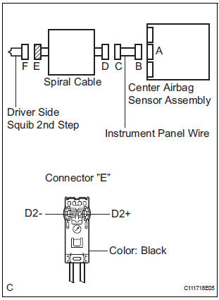
4 CHECK INSTRUMENT PANEL WIRE
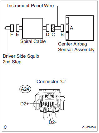
- Disconnect the instrument panel wire connector from the spiral cable.
- Measure the resistance according to the value(s) in the table below.
Standard resistance
5 CHECK SPIRAL CABLE
- Measure the resistance according to the value(s) in the table below.
Standard resistance
USE SIMULATION METHOD TO CHECK
 Open in Driver Side Squib 2nd Step Circuit
DTC B1181/18 Open in Driver Side Squib 2nd Step Circuit
DESCRIPTION
The driver side squib 2nd step circuit consists of the center airbag sensor
assembly, the spiral cable and
the steering pad.
...
 Short to B+ in Driver Side Squib 2nd Step Circuit
DTC B1183/22 Short to B+ in Driver Side Squib 2nd Step Circuit
DESCRIPTION
The driver side squib 2nd step circuit consists of the center airbag sensor
assembly, the spiral cable and
the steering ...
Other materials:
Removal
HINT:
Use the same procedures for the RH side and LH side.
The procedures listed below are for the LH side.
1. PRECAUTION
CAUTION:
Be sure to read "PRECAUTION" thoroughly before servicing.
2. DISCONNECT CABLE FROM NEGATIVE BATTERY
TERMINAL
CAUTION:
Wait for 90 seconds ...
Definition of terms
Terms
Definitions
Monitor Description
Description of what ECM monitors and how to detect malfunctions
(monitoring purpose and details).
Related DTCs
A group of diagnostic trouble codes that are output by ECM based on
the same malfunction detection lo ...
On-vehicle inspection
1. INSPECT BRAKE PEDAL HEIGHT
(a) Check the brake pedal height.
Pedal height from dash panel:
150.3 to 160.3 mm (5.917 to 6.311 in.)
NOTICE:
Do not adjust the pedal height. Doing so by
changing the push rod length will structurally
change the pedal ratio.
2. CHECK AND ADJUST STOP LIGHT S ...
