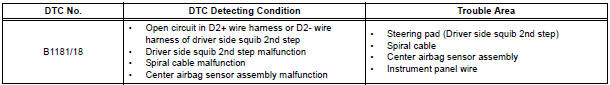
Toyota Sienna Service Manual: Open in Driver Side Squib 2nd Step Circuit
DTC B1181/18 Open in Driver Side Squib 2nd Step Circuit
DESCRIPTION
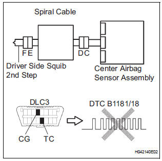
The driver side squib 2nd step circuit consists of the center airbag sensor assembly, the spiral cable and the steering pad.
The circuit instructs the SRS to deploy when deployment conditions are met.
DTC B1181/18 is recorded when an open circuit is detected in the driver side squib 2nd step circuit.
WIRING DIAGRAM
INSPECTION PROCEDURE
HINT:
- Perform the simulation method by selecting the "check mode" (signal check) with the intelligent tester.
- After selecting the "check mode" (signal check), perform the simulation method by wiggling each connector of the airbag system or driving the vehicle on a city or rough road
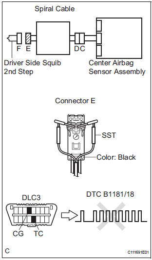
1 CHECK STEERING PAD (DRIVER SIDE SQUIB 2ND STEP)
- Turn the ignition switch to the LOCK position.
- Disconnect the negative (-) terminal cable from the battery, and wait for at least 90 seconds.
- Disconnect the connectors from the steering pad.
- Connect the white wire side of SST (resistance 2.1 Ω) to
the spiral cable.
CAUTION: Never connect a tester to the steering pad (driver side squib 2nd step) for measurement, as this may lead to a serious injury due to airbag deployment.
NOTICE: Do not forcibly insert the SST into the terminals of the connector when connecting.
Insert the SST straight into the terminals of the connector.
SST 09843-18060
- Connect the negative (-) terminal cable to the battery, and wait for at least 2 seconds.
- Turn the ignition switch to the ON position, and wait for at least 60 seconds.
- Clear the DTCs stored in memory.
- Turn the ignition switch to the LOCK position.
- Turn the ignition switch to the ON position, and wait for at least 60 seconds.
- Check the DTCs.
OK: DTC B1181/18 is not output.
HINT: Codes other than DTC B1181/18 may be output at this time, but they are not related to this check.
REPLACE STEERING PAD
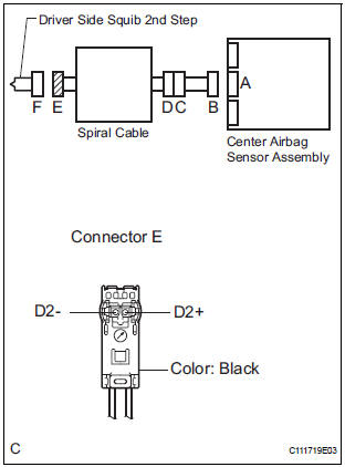
2 CHECK DRIVER SIDE SQUIB 2ND STEP CIRCUIT
- Turn the ignition switch to the LOCK position.
- Disconnect the negative (-) terminal cable from the battery, and wait for at least 90 seconds.
- Disconnect the SST (resistance 2.1 Ω) from the spiral cable.
- Disconnect the connector from the center airbag sensor assembly.
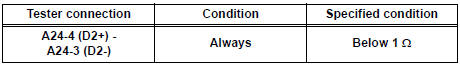
- Measure the resistance according to the value(s) in the table below.
Standard resistance
3 CENTER AIRBAG SENSOR ASSEMBLY
- Connect the connectors to the steering pad and the center airbag sensor assembly.
- Connect the negative (-) terminal cable to the battery, and wait for at least 2 seconds.
- Turn the ignition switch to the ON position, and wait for at least 60 seconds.
- Clear the DTCs stored in memory.
- Turn the ignition switch to the LOCK position.
- Turn the ignition switch to the ON position, and wait for at least 60 seconds.
- Check the DTCs.
OK: DTC B1181/18 is not output.
HINT: Codes other than DTC B1181/18 may be output at this time, but they are not related to this check.
USE SIMULATION METHOD TO CHECK
4 CHECK INSTRUMENT PANEL WIRE
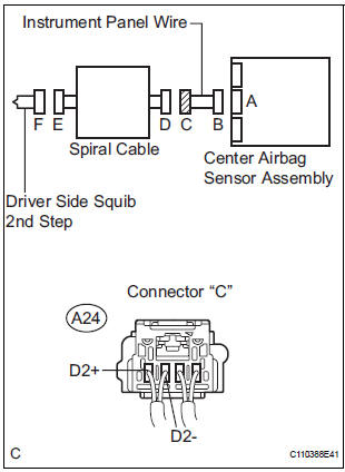
- Disconnect the instrument panel wire connector from the spiral cable.
- Measure the resistance according to the value(s) in the table below.
Standard resistance
5 CHECK SPIRAL CABLE
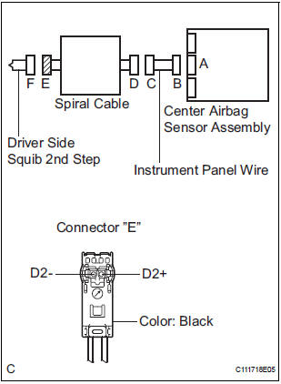
- Measure the resistance according to the value(s) in the table below.
Standard resistance
USE SIMULATION METHOD TO CHECK
 Short in Driver Side Squib 2nd Step Circuit
DTC B1180/17 Short in Driver Side Squib 2nd Step Circuit
DESCRIPTION
The driver side squib 2nd step circuit consists of the center airbag sensor
assembly, the spiral cable and
the steering pad.
...
 Short to GND in Driver Side Squib 2nd Step Circuit
DTC B1182/19 Short to GND in Driver Side Squib 2nd Step Circuit
DESCRIPTION
The driver side squib 2nd step circuit consists of the center airbag sensor
assembly, the spiral cable and
the steering ...
Other materials:
Removal
1. DISCHARGE FUEL SYSTEM PRESSURE
2. REMOVE V-BANK COVER SUB-ASSEMBLY
3. DRAIN ENGINE COOLANT
4. REMOVE WINDSHIELD WIPER MOTOR ASSEMBLY
5. REMOVE FRONT OUTER COWL TOP PANEL SUBASSEMBLY
6. REMOVE AIR CLEANER CAP SUB-ASSEMBLY
7. REMOVE AIR CLEANER CASE SUB-ASSEMBLY
8. REMOVE INTAKE AIR SURGE TA ...
Differential oil
Adjustment
1. INSPECT DIFFERENTIAL OIL
(a) Stop the vehicle on the level place.
(b) Remove the differential filler plug and gasket.
(c) Check that the oil surface is within 5 mm (0.20 in.)
from the lowest position of the inner surface of the
differential filler plug opening.
NOTICE:
...
Short in Front Pretensioner Squib RH Circuit
DTC B0130/63 Short in Front Pretensioner Squib RH Circuit
DESCRIPTION
The front pretensioner squib RH circuit consists of the center airbag sensor
assembly and the front seat
outer belt assembly RH.
This circuit instructs the SRS to deploy when deployment conditions are met.
DTC B0130/63 ...
