Toyota Sienna Service Manual: Short to GND in Front Passenger Side Squib 2nd Step Circuit
DTC B1187/55 Short to GND in Front Passenger Side Squib 2nd Step Circuit
DESCRIPTION
The front passenger side squib 2nd step circuit consists of the center airbag sensor assembly and the front passenger airbag assembly.
The circuit instructs the SRS to deploy when deployment conditions are met.
DTC B1187/55 is recorded when a short to ground is detected in the front passenger side squib 2nd step circuit.
|
DTC No. |
DTC Detecting Condition |
Trouble Area |
|
B1187/55 |
|
|
INSPECTION PROCEDURE
HINT:
- Perform the simulation method by selecting the "check mode" (signal check) with the intelligent tester (8).
- After selecting the "check mode" (signal check), perform the simulation method by wiggling each connector of the airbag system or driving the vehicle on a city or rough road
1 CHECK FRONT PASSENGER AIRBAG ASSEMBLY (FRONT PASSENGER SIDE SQUIB 2ND STEP)
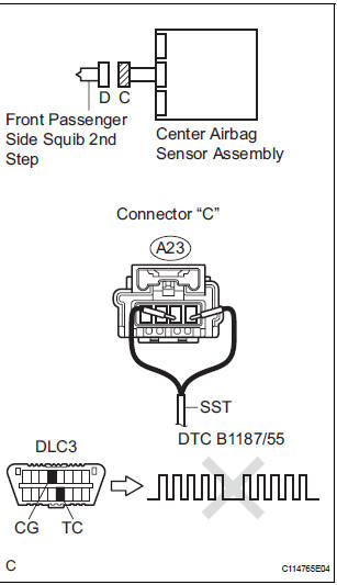
- Turn the ignition switch to the LOCK position.
- Disconnect the negative (-) terminal cable from the battery, and wait for at least 90 seconds.
- Disconnect the connectors from the front passenger airbag assembly.
- Connect the black wire side of SST (resistance 2.1 Ω) to the instrument panel wire.
CAUTION: Never connect a tester to the front passenger airbag assembly (front passenger side squib 2nd step) for measurement, as this may lead to a serious injury due to airbag deployment.
NOTICE: Do not forcibly insert the SST into the terminals of the connector when connecting.
Insert the SST straight into the terminals of the connector.
SST 09843-18060
- Connect the negative (-) terminal cable to the battery, and wait for at least 2 seconds.
- Turn the ignition switch to the ON position, and wait for at least 60 seconds.
- Clear the DTCs stored in memory (5).
- Turn the ignition switch to the LOCK position.
- Turn the ignition switch to the ON position, and wait for at least 60 seconds.
- Check the DTCs (5).
OK: DTC B1187/55 is not output. HINT: Codes other than DTC B1187/55 may be output at this time, but they are not related to this check.
 Go to step 2

REPLACE FRONT PASSENGER AIRBAG ASSEMBLY
2 CHECK INSTRUMENT PANEL WIRE (FRONT PASSENGER SIDE SQUIB 2ND STEP CIRCUIT)
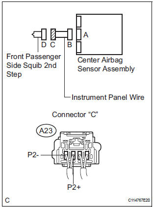
- Turn the ignition switch to the LOCK position.
- Disconnect the negative (-) terminal cable from the battery, and wait for at least 90 seconds.
- Disconnect the SST (resistance 2.1 Ω) from the instrument panel wire.
- Disconnect the connector from the center airbag sensor assembly.
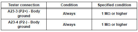
- Measure the resistance according to the value(s) in the table below.
Standard resistance
 REPAIR OR REPLACE INSTRUMENT
PANEL
WIRE
REPAIR OR REPLACE INSTRUMENT
PANEL
WIRE

3 CHECK CENTER AIRBAG SENSOR ASSEMBLY
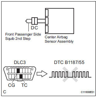
- Connect the connectors to the front passenger airbag assembly and the center airbag sensor assembly.
- Connect the negative (-) terminal cable to the battery, and wait for at least 2 seconds.
- Turn the ignition switch to the ON position, and wait for at least 60 seconds.
- Clear the DTCs stored in memory (5).
- Turn the ignition switch to the LOCK position.
- Turn the ignition switch to the ON position, and wait for at least 60 seconds.
- Check the DTCs (5).
OK: DTC B1187/55 is not output. HINT: Codes other than DTC B1187/55 may be output at this time, but they are not related to this check.
 REPLACE CENTER AIRBAG SENSOR
ASSEMBLY
REPLACE CENTER AIRBAG SENSOR
ASSEMBLY

USE SIMULATION METHOD TO CHECK
 Open in Front Passenger Side Squib 2nd Step
Circuit
Open in Front Passenger Side Squib 2nd Step
Circuit
DTC B1186/58 Open in Front Passenger Side Squib 2nd Step
Circuit
DESCRIPTION
The front passenger side squib 2nd step circuit consists of the center airbag
sensor assembly and the
front passenger ...
 Short to B+ in Front Passenger Side Squib 2nd
Step Circuit
Short to B+ in Front Passenger Side Squib 2nd
Step Circuit
DTC B1188/56 Short to B+ in Front Passenger Side Squib 2nd
Step Circuit
DESCRIPTION
The front passenger side squib 2nd step circuit consists of the center airbag
sensor assembly and the
front pa ...
Other materials:
Dtc check / clear
1. DTC CHECK/CLEAR (WHEN USING SST CHECK WIRE):
(a) DTC check
(1) Using SST, connect terminals TC and CG of the
DLC3.
SST 09843-18040
(2) Turn the ignition switch to the ON position.
(3) Read the DTCs from the ABS warning light on
the combination meter.
HINT:
If no code appears, inspe ...
Rear Occupant Classification Sensor RH Collision
Detection
DTC B1788 Rear Occupant Classification Sensor RH Collision
Detection
DESCRIPTION
DTC B1788 is output when the occupant classification ECU receives a collision
detection signal sent by
the rear occupant classification sensor RH if an accident occurs.
DTC B1788 is also output when the front s ...
Power back door opener / closer switch
INSPECTION
1. INSPECT SATELLITE SWITCH
Inspect the resistance of the back door switch.
Resistance
If the result is not as specified, replace the switch.
Apply battery voltage and check whether the switch
illuminates.
Standard
HINT:
Whether the switch illuminates or not wi ...
