Toyota Sienna Service Manual: Short to GND in Front Pretensioner Squib RH Circuit
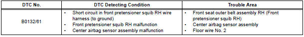
DTC B0132/61 Short to GND in Front Pretensioner Squib RH Circuit
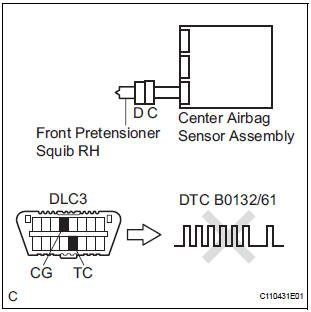
DESCRIPTION
The front pretensioner squib RH circuit consists of the center airbag sensor assembly and the front seat outer belt assembly RH.
This circuit instructs the SRS to deploy when deployment conditions are met.
DTC B0132/61 is recorded when a short to ground is detected in the front pretensioner squib RH circuit.
WIRING DIAGRAM
INSPECTION PROCEDURE
HINT:
- Perform the simulation method by selecting the "check mode" (signal check) with the intelligent tester.
- After selecting the "check mode" (signal check), perform the simulation method by wiggling each connector of the airbag system or driving the vehicle on a city or rough road
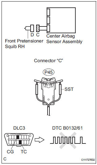
1 CHECK FRONT SEAT OUTER BELT ASSEMBLY RH (FRONT PRETENSIONER SQUIB RH)
- Turn the ignition switch to the LOCK position.
- Disconnect the negative (-) terminal cable from the battery, and wait for at least 90 seconds.
- Disconnect the connectors from the front seat outer belt assembly RH.
- Connect the white wire side of SST (resistance 2.1 Ω) to the floor wire No. 2.
CAUTION: Never connect a tester to the front seat outer belt assembly RH (front pretensioner squib RH) for measurement, as this may lead to a serious injury due to airbag deployment.
NOTICE: Do not forcibly insert the SST into the terminals of the connector when connecting.
Insert the SST straight into the terminals of the connector.
SST 09843-18060
- Connect the negative (-) terminal cable to the battery, and wait for at least 2 seconds.
- Turn the ignition switch to the ON position, and wait for at least 60 seconds.
- Clear the DTCs stored in memory.
- Turn the ignition switch to the LOCK position.
- Turn the ignition switch to the ON position, and wait for at least 60 seconds.
- Check the DTCs.
OK: DTC B0132/61 is not output.
HINT: Codes other than DTC B0132/61 may be output at this time, but they are not related to this check.
REPLACE FRONT SEAT OUTER BELT ASSEMBLY RH
2 CHECK FLOOR WIRE NO.2 (FRONT PRETENSIONER SQUIB RH CIRCUIT)
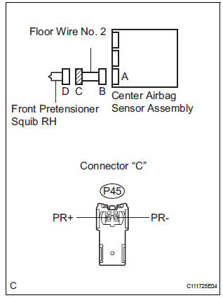
- Turn the ignition switch to the LOCK position.
- Disconnect the negative (-) terminal cable from the battery, and wait for at least 90 seconds.
- Disconnect the SST (resistance 2.1 Ω) from the floor wire No. 2.
- Disconnect the connector from the center airbag sensor assembly.
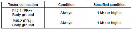
- Measure the resistance according to the value(s) in the table below.
Standard resistance
3 CHECK CENTER AIRBAG SENSOR ASSEMBLY
- Connect the connectors to the front seat outer belt assembly RH and the center airbag sensor assembly.
- Connect the negative (-) terminal cable to the battery, and wait for at least 2 seconds.
- Turn the ignition switch to the ON position, and wait for at least 60 seconds.
- Clear the DTCs stored in memory.
- Turn the ignition switch to the LOCK position.
- Turn the ignition switch to the ON position, and wait for at least 60 seconds.
- Check the DTCs.
OK: DTC B0132/61 is not output.
HINT: Codes other than code B0132/61 may be output at this time, but they are not related to this check.
USE SIMULATION METHOD TO CHECK
 Open in Front Pretensioner Squib RH Circuit
DTC B0131/64 Open in Front Pretensioner Squib RH Circuit
DESCRIPTION
The front pretensioner squib RH circuit consists of the center airbag sensor
assembly and the front seat
outer belt assembly R ...
 Short to B+ in Front Pretensioner Squib RH Circuit
DTC B0133/62 Short to B+ in Front Pretensioner Squib RH Circuit
DESCRIPTION
The front pretensioner squib RH circuit consists of the center airbag sensor
assembly and the front seat
outer belt ass ...
Other materials:
Installation
1. INSTALL SLIDE DOOR ROLLER ASSEMBLY UPPER
Apply MP grease to the rotating areas of the roller.
Install the roller with the 2 bolts.
Torque: 13 N*m (130 kgf*cm, 10 ft.*lbf)
2. INSTALL SLIDE DOOR HINGE ASSEMBLY CENTER LH
Apply MP grease to the rotating areas of the hinge.
In ...
Reassembly
1. INSTALL 2ND BRAKE PISTON O-RING
(a) Coat 2 new O-rings with ATF, and install them in the
2nd brake piston.
NOTICE:
Make sure that the O-ring is not twisted or
pinched.
2. INSTALL 2ND BRAKE PISTON
(a) Coat the 2nd brake piston with ATF, and install it to
the 2nd brake cylinder.
NO ...
Maintenance data
(fuel, oil level, etc.)
Dimensions and weights
*1: Unladen vehicle
*2: The model code is indicated on the Certification Label. For details, see
ŌĆ£Vehicle identificationŌĆØ below.
*3: The towing package is required.
Toyota does not recommend towing with this vehicle without the towing
package.
Vehicle identifi ...
