Toyota Sienna Service Manual: Master Reset/ Voice Processing Device ON Error
DTC 01-DD Master Reset
DTC 01-E1 Voice Processing Device ON Error
DESCRIPTION
HINT:
*1: This code may be stored if the engine is started and the ignition switch is
turned to START position
again.
*2: Even if no fault is present, this trouble code may be stored depending on
the battery condition or
engine start voltage.
NOTICE:
- Before starting troubleshooting, be sure to clear DTCs to erase codes stored due to the reasons described in the HINT above. Then, check for DTCs and troubleshoot according to the output DTCs.
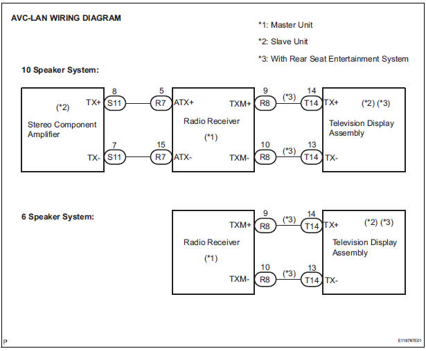
- The radio receiver is the master unit.
- Be sure to clear and recheck DTCs after the inspection is completed to confirm that no DTCs are output.
INSPECTION PROCEDURE
NOTICE: Be sure to read DESCRIPTION before performing the following procedures.
1 CHECK RADIO RECEIVER POWER SOURCE CIRCUIT
Refer to the radio receiver power source circuit.
If the power source circuit is operating normally, proceed to the next step.
2 INSPECT RADIO RECEIVER
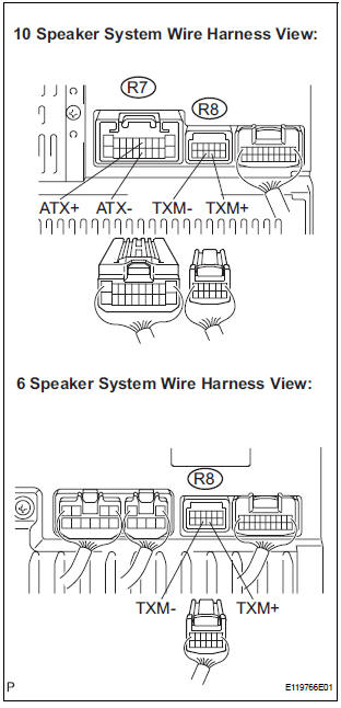
- Disconnect the radio receiver connector.
- Measure the resistance according to the value(s) in the table below.
Standard resistance
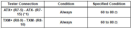
*1: 10 Speaker System
3 IDENTIFY THE COMPONENT WHICH HAS STORED THIS CODE
- Enter the diagnostic mode.
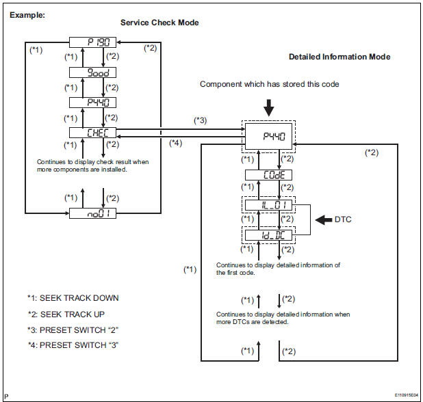
- Press the preset switch "3" to change to "Detailed Information Mode".
- Identify the component which has stored this code.
Component Table

HINT:
- "440 (stereo component amplifier)" is the component which has stored this code in the example shown in the illustration.
- For details of the DTC display, refer to "DTC CHECK/ CLEAR"
4 CHECK HARNESS AND CONNECTOR (RADIO RECEIVER - COMPONENT WHICH HAS STORED THIS CODE)
HINT: For details of the connectors, refer to the "TERMINALS OF ECU".
- Referring to the AVC-LAN wiring diagram below, check the AVC-LAN circuit between the radio receiver and the component which has stored this code.
- Disconnect all connectors between the radio receiver and the component which has stored this code.
- Check for an open or short in the AVC-LAN circuit between the radio receiver and the component which has stored this code.
OK: There is no open or short circuit.
5 REPLACE RADIO RECEIVER
- Replace the radio receiver with a normal one and check if the same problem occurs again.
OK: Same problem does not occur.
END
 Transmission Error
DTC 01-DC Transmission Error
DESCRIPTION
HINT:
*1: This code may be stored if the engine is started, idled for 60 seconds and
then started again.
NOTICE:
Before starting troubl ...
 Master Error
DTC 01-DF Master Error
DESCRIPTION
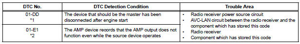
DTC No.
DTC Detection Condition
Trouble Area
01-DF
*1
The device with a display fails and the master is
switched to ...
Other materials:
Catalyst System Efficiency Below Threshold
DTC P0420 Catalyst System Efficiency Below Threshold
(Bank 1)
DTC P0430 Catalyst System Efficiency Below Threshold
(Bank 2)
MONITOR DESCRIPTION
The ECM uses the sensors mounted in front of and behind the three-way
catalyst (TWC) to monitor its
efficiency. The first sensor, an Air Fuel ratio ...
Personal/interior
lights
Front
Turns the light on/off
Rear
Turns the light on/off
When the personal/interior light main switch is in the off position, the
rear personal lights will not turn on even if the switch is on.
Type A
Type B
...
Brake Warning Light Remains ON
DESCRIPTION
The BRAKE warning light comes on when the brake fluid is insufficient, the
parking brake is applied or the
EBD is defective.
WIRING DIAGRAM
INSPECTION PROCEDURE
HINT:
When releasing the parking brake, move the shift lever into the P position in an
AT vehicle, and choke in
...
