Toyota Sienna Service Manual: Short to GND in Side Squib LH Circuit
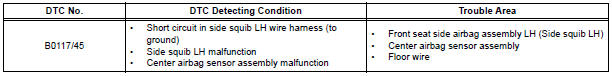
DTC B0117/45 Short to GND in Side Squib LH Circuit
DESCRIPTION
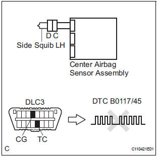
The side squib LH circuit consists of the center airbag sensor assembly and the front seat side airbag assembly LH.
This circuit instructs the SRS to deploy when deployment conditions are met.
DTC B0117/45 is recorded when a short to ground is detected in the side squib LH circuit.
WIRING DIAGRAM
INSPECTION PROCEDURE
HINT:
- Perform the simulation method by selecting the "check mode" (signal check) with the intelligent tester.
- After selecting the "check mode" (signal check), perform the simulation method by wiggling each connector of the airbag system or driving the vehicle on a city or rough road
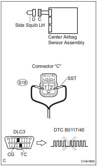
1 CHECK FRONT SEAT SIDE AIRBAG ASSEMBLY LH (SIDE SQUIB LH)
- Turn the ignition switch to the LOCK position.
- Disconnect the negative (-) terminal cable from the battery, and wait for at least 90 seconds.
- Disconnect the connectors from the front seat side airbag assembly LH.
- Connect the black wire side of SST (resistance 2.1 Ω) to the floor wire.
CAUTION: Never connect a tester to the front seat side airbag assembly LH (side squib LH) for measurement, as this may lead to a serious injury due to airbag deployment.
NOTICE: Do not forcibly insert the SST into the terminals of the connector when connecting.
Insert the SST straight into the terminals of the connector.
SST 09843-18060
- Connect the negative (-) terminal cable to the battery, and wait for at least 2 seconds.
- Turn the ignition switch to the ON position, and wait for at least 60 seconds.
- Clear the DTCs stored in memory.
- Turn the ignition switch to the LOCK position.
- Turn the ignition switch to the ON position, and wait for at least 60 seconds.
- Check the DTCs
OK: DTC B0117/45 is not output.
HINT: Codes other than DTC B0117/45 may be output at this time, but they are not related to this check.
REPLACE FRONT SEAT ASSEMBLY LH
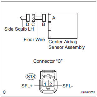
2 CHECK FLOOR WIRE (SIDE SQUIB LH CIRCUIT)
- Turn the ignition switch to the LOCK position.
- Disconnect the negative (-) terminal cable from the battery, and wait for at least 90 seconds.
- Disconnect the SST (resistance 2.1 Ω) from the floor wire.
- Disconnect the connector from the center airbag sensor assembly.
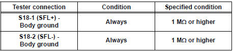
- Measure the resistance according to the value(s) in the table below.
Standard resistance
3 CHECK CENTER AIRBAG SENSOR ASSEMBLY
- Connect the connectors to the front seat side airbag assembly LH and the center airbag sensor assembly.
- Connect the negative (-) terminal cable to the battery, and wait for at least 2 seconds.
- Turn the ignition switch to the ON position, and wait for at least 60 seconds.
- Clear the DTCs stored in memory.
- Turn the ignition switch to the LOCK position.
- Turn the ignition switch to the ON position, and wait for at least 60 seconds.
- Check the DTCs.
OK: DTC B0117/45 is not output.
HINT: Codes other than code B0117/45 may be output at this time, but they are not related to this check.
USE SIMULATION METHOD TO CHECK
 Open in Side Squib LH Circuit
DTC B0116/48 Open in Side Squib LH Circuit
DESCRIPTION
The side squib LH circuit consists of the center airbag sensor assembly and
the front seat side assembly
LH.
This circuit instructs the S ...
 Short to B+ in Side Squib LH Circuit
DTC B0118/46 Short to B+ in Side Squib LH Circuit
DESCRIPTION
The side squib LH circuit consists of the center airbag sensor assembly and
the front seat side airbag
assembly LH (side squib LH).
...
Other materials:
DTC check / clear
1. CHECK DTC
Prepare the intelligent tester.
Connect the intelligent tester to DLC3.
Turn the ignition switch to the ON position and turn
the intelligent tester main switch ON.
Use the intelligent tester to check the DTCs, and
note them down (For operating instructions, see the
int ...
Stop Light Switch Circuit Malfunction
DTC P0571 Stop Light Switch Circuit Malfunction
DESCRIPTION
The ECM receives the brake demand signal from the distance control ECU and
transmits it to the skid
control ECU (brake actuator assembly).
The skid control ECU (brake actuator assembly) receives a signal from the ECM
and operates ...
Communication Error of Yaw Rate Sensor
DTC U0123 Communication Error of Yaw Rate Sensor
DESCRIPTION
This circuit detects the yaw rate of the vehicle and transmits its signal to
the skid control ECU and
distance control ECU.
DTC No.
DTC Detection Condition
Trouble Area
U0123
While the dynamic ...
