Toyota Sienna Service Manual: Adjustment
HINT:
- On the RH side, use the same procedures as on the LH side.
- Since a centering bolt is used as a door hinge mounting bolt on the body side and the door side, the door can not be adjusted with it on. Substitute a bolt with a washer for the centering bolt.
1. INSPECT FRONT DOOR PANEL SUB-ASSEMBLY LH
- Check that the clearance is within the standard range.
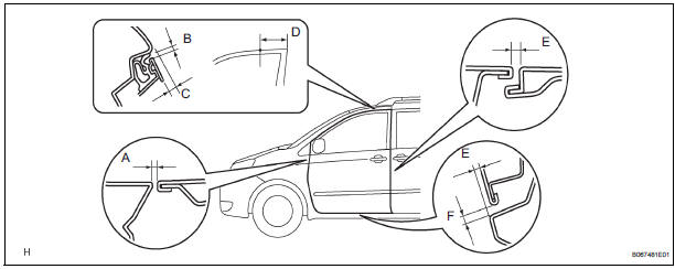
Standard

2. ADJUST FRONT DOOR PANEL SUB-ASSEMBLY LH
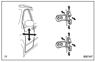
- Using SST, horizontally and vertically adjust the
door by loosening the body side hinge bolts.
SST 09812-00010, 09812-00020
- Tighten the door side hinge bolts after the
adjustment.
Torque: 26 N*m (265 kgf*cm, 19 ft.*lbf)
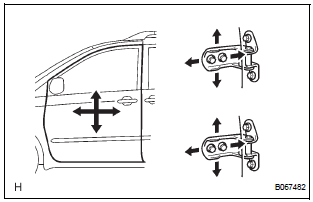
- Adjust the door forward / rearward and vertically by loosening the door side hinge bolts.
- Tighten the door side hinge bolts after the
adjustment.
Torque: 26 N*m (265 kgf*cm, 19 ft.*lbf)
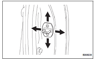
- Adjust the striker position by slightly loosening the striker mounting screws and hitting the striker with a plastic-faced hammer.
- Tighten the striker mounting screws after the
adjustment.
Torque: 23 N*m (235 kgf*cm, 17 ft.*lbf)
 Disassembly
HINT:
On the RH side, use the same procedures as on the LH side.
1. REMOVE FRONT DOOR LOWER FRAME BRACKET GARNISH LH
Using a screwdriver, disengage the clip and claw,
and remove the garnis ...
 Reassembly
1. INSTALL FRONT DOOR WIRE LH
Install the wire with the 2 bolts.
Torque: Reference
8.0 N*m (82 kgf*cm, 71 in.*lbf)
NOTICE:
In order to prevent water leakage, be sure that
the lip of t ...
Other materials:
Air conditioning
SST
RECOMMENDED TOOLS
HINT:
Torx is a registered trademark of Textron Inc.
EQUIPMENT
LUBRICANT
SUPPLEMENTAL RESTRAINT SYSTEM
SST
RECOMMENDED TOOLS
HINT:
Torx is a registered trademark of Textron lnc.
EQUIPMENT
SEAT BELT
SST
RECOMMENDED TOOLS
EQUIPMENT
THEFT ...
Checking tires
Check if the treadwear indicators are showing on the tires. Also check
the tires for uneven wear, such as excessive wear on one side of the
tread. Check the spare tire condition and pressure if not rotated.
New tread
Worn tread
Treadwear indicator
The location of treadwear indicator ...
Installation
1. INSTALL REAR AXLE HUB & BEARING ASSEMBLY LH
(a) Install the hub & bearing assembly LH with the 4
bolts.
Torque: 56 N*m (571 kgf*cm, 41 ft.*lbf)
2. INSPECT BEARING BACKLASH (See page AH-19)
3. INSPECT AXLE HUB DEVIATION (See page AH-19)
4. INSTALL REAR DRIVE SHAFT ASSEMBLY LH (Se ...
