Toyota Sienna Service Manual: Side Airbag Sensor Assembly LH Circuit Malfunction
DTC B1141/33 Side Airbag Sensor Assembly LH Circuit Malfunction
DESCRIPTION
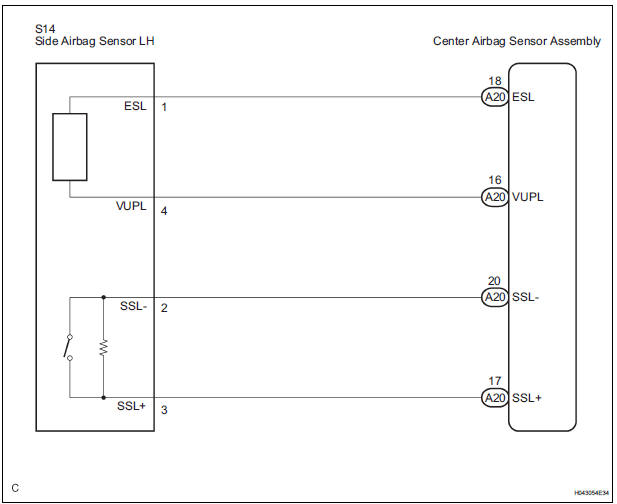
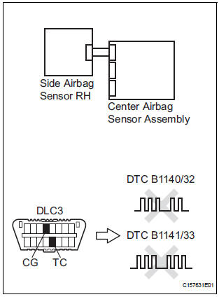
The side airbag sensor LH circuit consists of the center airbag sensor assembly and side airbag sensor LH.
If the center airbag sensor assembly receives signals from the side airbag sensor LH, it judges whether or not the SRS should be activated.
DTC B1141/33 is recorded when a malfunction in the side airbag sensor LH circuit is detected.
|
DTC No. |
DTC Detecting Condition |
Trouble Area |
|
B1141/33 |
|
|
WIRING DIAGRAM
INSPECTION PROCEDURE
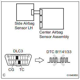
1 CHECK DTC
- Turn the ignition switch to the ON position, and wait for at least 60 seconds.
- Clear the DTCs stored in memory (5).
- Turn the ignition switch to the LOCK position.
- Turn the ignition switch to the ON position, and wait for at least 60 seconds.
- Check the DTCs (5).
OK: DTC B1141/33 is not output. HINT: Codes other than DTC B1141/33 may be output at this time, but they are not related to this check.
 Go to step 2

USE SIMULATION METHOD TO CHECK
2 CHECK CONNECTION OF CONNECTORS
- Turn the ignition switch to the LOCK position.
- Disconnect the negative (-) terminal cable from the battery, and wait for at least 90 seconds.
- Check that the connectors are properly connected to the center airbag sensor assembly and the side airbag sensor LH.
OK: The connectors are connected.
 CONNECT CONNECTORS

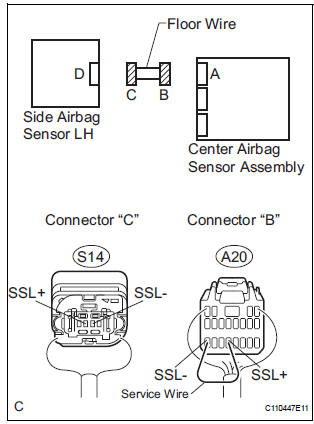
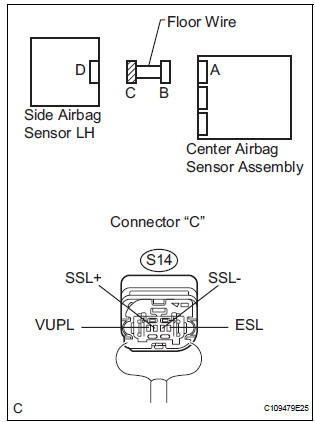
3 CHECK FLOOR WIRE (OPEN)
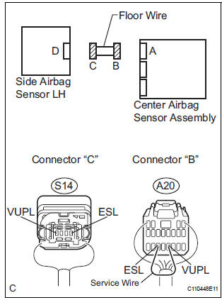
- Disconnect the connectors from the center airbag sensor assembly and the side airbag sensor LH.
- Using a service wire, connect A20-16 (VUPL) and A20-
18 (ESL) of connector "B".
NOTICE: Do not forcibly insert a service wire into the terminals of the connector when connecting.
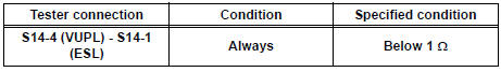
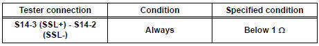
- Measure the resistance according to the value(s) in the table below.
Standard resistance
- Using a service wire, connect A20-17 (SSL+) and A20-
20 (SSL-) of connector "B".
NOTICE: Do not forcibly insert a service wire into the terminals of the connector when connecting.
- Measure the resistance according to the value(s) in the table below.
Standard resistance
 REPAIR OR REPLACE FLOOR WIRE

4 CHECK FLOOR WIRE (SHORT TO B+)
- Disconnect the service wire from connector "B".
- Connect the negative (-) terminal cable to the battery, and wait for at least 2 seconds.
- Turn the ignition switch to the ON position.
- Measure the voltage according to the value(s) in the table below.
Standard voltage
 REPAIR OR REPLACE FLOOR WIRE

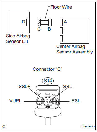
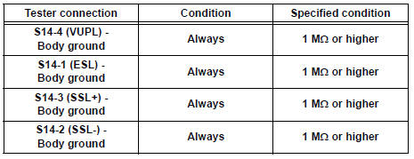
5 CHECK FLOOR WIRE (SHORT TO GROUND)
- Turn the ignition switch to the LOCK position.
- Disconnect the negative (-) terminal cable from the battery, and wait for at least 90 seconds.
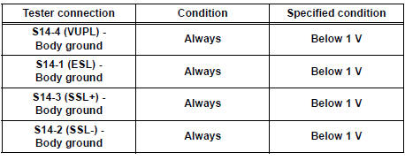
- Measure the resistance according to the value(s) in the table below.
Standard resistance
 REPAIR OR REPLACE FLOOR WIRE

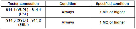
6 CHECK FLOOR WIRE (SHORT)
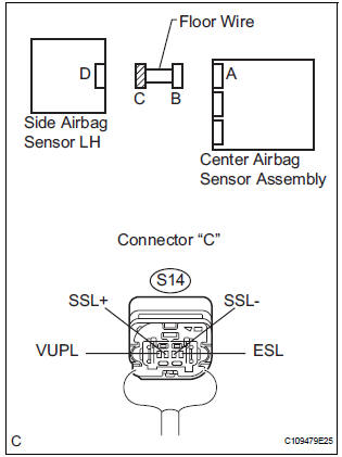
- Measure the resistance according to the value(s) in the table below.
Standard resistance
 REPAIR OR REPLACE FLOOR WIRE

7 CHECK SIDE AIRBAG SENSOR LH
- Connect the connector to the center airbag sensor assembly.
- Interchange the side airbag sensor RH with LH and connect the connectors to them.
- Connect the negative (-) terminal cable to the battery, and wait for at least 2 seconds.
- Turn the ignition switch to the ON position, and wait for at least 60 seconds.
- Clear the DTCs stored in memory (5).
- Turn the ignition switch to the LOCK position.
- Turn the ignition switch to the ON position, and wait for at least 60 seconds.
- Check the DTCs (5).
Result
HINT: Codes other than DTC B1140/32 and B1141/33 may be output at this time, but they are not related to this check.
 REPLACE SIDE AIRBAG SENSOR
LH
REPLACE SIDE AIRBAG SENSOR
LH
 REPLACE CENTER AIRBAG SENSOR
ASSEMBLY
REPLACE CENTER AIRBAG SENSOR
ASSEMBLY

USE SIMULATION METHOD TO CHECK
 Side Airbag Sensor Assembly RH Circuit Malfunction
DTC B1140/32 Side Airbag Sensor Assembly RH Circuit Malfunction
DESCRIPTION
The side airbag sensor RH circuit consists of the center airbag sensor
assembly and side airbag sensor
RH.
If the ce ...
 Front Airbag Sensor RH Circuit Malfunction
DTC B1148/36 Front Airbag Sensor RH Circuit Malfunction
DESCRIPTION
The front airbag sensor RH circuit consists of the center airbag sensor
assembly and front airbag sensor
RH. If the center airb ...
Other materials:
Removal
1. REMOVE FRONT DOOR OPENING TRIM
WEATHERSTRIP LH
2. REMOVE FRONT DOOR OPENING TRIM
WEATHERSTRIP RH
3. REMOVE FRONT PILLAR GARNISH LH
4. REMOVE FRONT PILLAR GARNISH RH
5. REMOVE VISOR ASSEMBLY LH
6. REMOVE VISOR ASSEMBLY RH
7. REMOVE ASSIST GRIP SUB-ASSEMBLY (2)
8. REMOVE VISOR HOLDER (1)
...
Adjusting the set speed
To change the set speed, operate the lever until the desired set speed
is obtained.
Increases the speed
Decreases the speed
Fine adjustment: Momentarily
move the lever in the desired direction.
Large adjustment: Hold the lever in
the desired direction.
The set speed will be incre ...
Deactivating or stopping the alarm
Do one of the following to deactivate or stop the alarm:
Unlock the doors using the entry function (vehicles with a smart
key
system) or wireless remote control.
Vehicles without a smart key system: Turn the engine switch to the
“ACC” or “ON” position, or start the engine.
Veh ...
