Toyota Sienna Service Manual: A/F Sensor Circuit Slow Response
HINT:
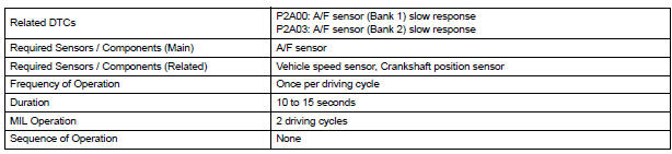
- DTC P2A00 indicates malfunctions related to the bank 1 A/F sensor.
- DTC P2A03 indicates malfunctions related to the bank 2 A/F sensor.
- Bank 1 refers to the bank that includes cylinder No. 1.
- Bank 2 refers to the bank that includes cylinder No. 2.
- Sensor 1 refers to the sensor mounted in front of the Three-Way Catalytic Converter (TWC) and located near the engine assembly.
DESCRIPTION
Refer to DTC P2195 (See page ES-355).
MONITOR DESCRIPTION
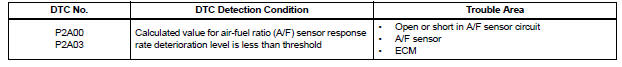
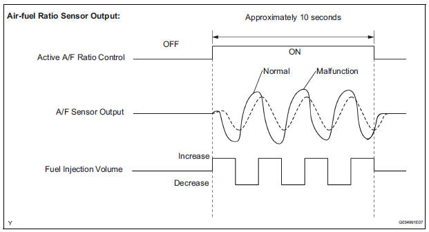
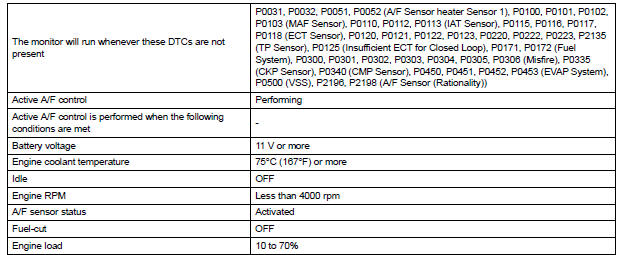
After the engine is warmed up, the ECM performs air-fuel ratio feedback control to maintain the air-fuel ratio at the stoichiometric level. In addition, active A/F ratio control is performed for approximately 10 seconds after preconditions are met in order to measure the A/F sensor response rate. During active A/F ratio control, the ECM forcibly increases and decreases the injection volume to a certain amount, based on the stoichiometric air-fuel ratio learned during normal air-fuel ratio control, and measures the A/F sensor response rate. The ECM receives a signal from the A/F sensor while performing active A/F ratio control and uses it to calculate the A/F sensor response rate deterioration level.
If the value for A/F sensor response rate deterioration level is less than the threshold, the ECM interprets this as a malfunction and sets the DTC.
CONFIRMATION DRIVING PATTERN
HINT:
Performing this confirmation driving pattern will activate the A/F sensor response monitor.
1. Connect the intelligent tester to the DLC3.
2. Turn the ignition switch to the ON position.
3. Turn the tester on.
4. Clear the DTCs (where set).
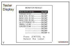
5. Select the following menu items: DIAGNOSIS / ENHANCED OBD II / MONITOR INFO / MONITOR RESULT.
6. Check that RES RATE B1S1 and RES RATE B2S1 is INCOMPL.
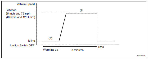
7. Start the engine and warm it up (Procedure "A").
8. Drive the vehicle at between 25 mph and 75 mph (40 km/h and 120 km/h) for 3 minutes. However, the vehicle should be driven at a constant speed (Procedure "B").
9. Check the monitor result values on the intelligent tester by selecting the following menu items: DIAGNOSIS / ENHANCED OBD II / MONITOR INFO / MONITOR RESULT /RES RATE B1S1 and RES RATE B2S1 / Enter.
10. If the values indicated on the tester do not change, perform READINESS MONITOR DRIVE PATTERN for the A/F sensor and the heated oxygen sensor (See page ES-22).
HINT:
Completion of all A/F sensor monitors is required to change the value in test result.
11. Note the value of the Monitor Result.
12. Select the following menu items: DIAGNOSIS / ENHANCED OBD II / DTC INFO / PENDING CODES.
13. Check if any DTCs (any pending DTCs) are set.
MONITOR STRATEGY
TYPICAL ENABLING CONDITIONS

TYPICAL MALFUNCTION THRESHOLDS

MONITOR RESULT
Refer to CHECKING MONITOR STATUS (See page ES-19).
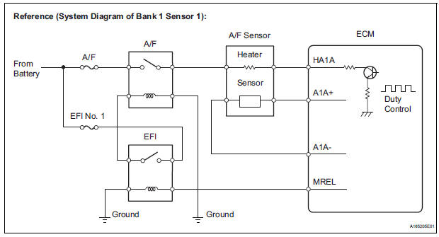
WIRING DIAGRAM
Refer to DTC P2195 (See page ES-359).
INSPECTION PROCEDURE
HINT:
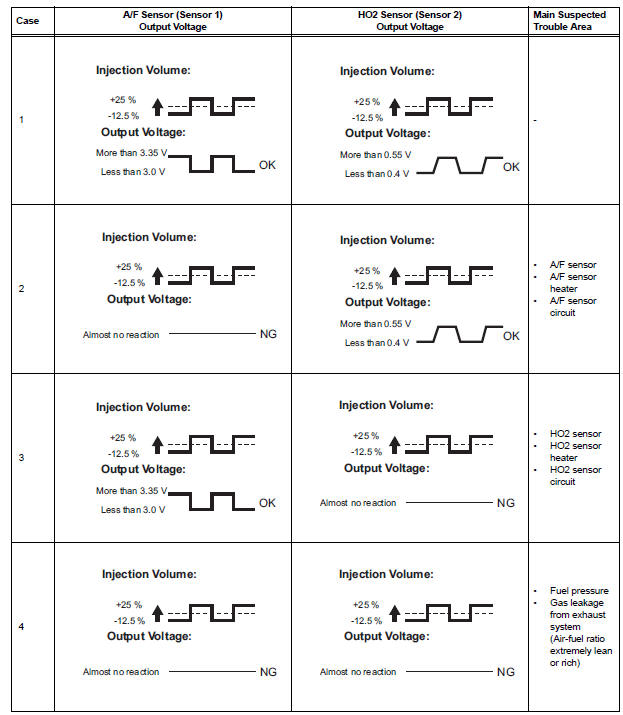
Malfunctioning areas can be identified by performing the A/F CONTROL function provided in the ACTIVE TEST. The A/F CONTROL function can help to determine whether the Air-Fuel Ratio (A/F) sensor, Heated Oxygen (HO2) sensor and other potential trouble areas are malfunctioning.
The following instructions describe how to conduct the A/F CONTROL operation using an intelligent tester.
(a) Connect the intelligent tester to the DLC3.
(b) Start the engine and turn the tester on.
(c) Warm up the engine at an engine speed of 2500 rpm for approximately 90 seconds.
(d) Select the following menu items on the tester: DIAGNOSIS / ENHANCED OBD II / ACTIVE TEST / A/ F CONTROL.
(e) Perform the A/F CONTROL operation with the engine in an idling condition (press the RIGHT or LEFT button to change the fuel injection volume).
(f) Monitor the voltage outputs of the A/F and HO2 sensors (AFS B1S1 and O2S B1S2 or AFS B2S1 and O2S B2S2) displayed on the tester.
HINT:
- The A/F CONTROL operation lowers the fuel injection volume by 12.5% or increases the injection volume by 25%.
- Each sensor reacts in accordance with increases and decreases in the fuel injection volume.
Standard voltage 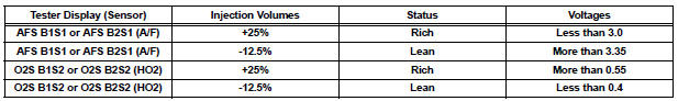
| NOTICE: The Air-Fuel Ratio (A/F) sensor has an output delay of a few seconds and the Heated Oxygen (HO2) sensor has a maximum output delay of approximately 20 seconds. |
- Following the A/F CONTROL procedure enables technicians to check and graph the voltage outputs of both the A/F and HO2 sensors.
- To display the graph, select the following menu items on the tester: DIAGNOSIS / ENHANCED OBD II / ACTIVE TEST / A/F CONTROL / USER DATA / AFS B1S1 and O2S B1S2 or AFS B2S1 and O2S B2S2. Press the YES button and then the ENTER button. Then press the F4 button.
HINT:
- DTC P2A00 or P2A03 may be also set when the air-fuel ratio is stuck rich or lean.
- A low A/F sensor voltage could be caused by a rich air-fuel mixture. Check for conditions that would cause the engine to run rich.
- A high A/F sensor voltage could be caused by a lean air-fuel mixture. Check for conditions that would cause the engine to run lean
- Read freeze frame data using the intelligent tester. The ECM records vehicle and driving condition information as freeze frame data the moment a DTC is stored. When troubleshooting, freeze frame data can be helpful in determining whether the vehicle was running or stopped, whether the engine was warmed up or not, whether the air-fuel ratio was lean or rich, as well as other data recorded at the time of a malfunction.
1 CHECK ANY OTHER DTCS OUTPUT (IN ADDITION TO DTC P2A00 AND/OR P2A03)
(a) Connect the intelligent tester to the DLC3.
(b) Turn the ignition switch to the ON position.
(c) Turn the tester on.
(d) Select the following menu items: DIAGNOSIS / ENHANCED OBD II / DTC INFO / CURRENT CODES.
(e) Read the DTCs.
Result 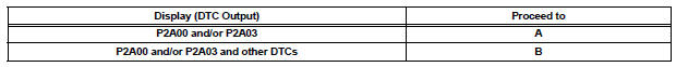
HINT:
If any DTCs other than P2A00 or P2A03 are output, troubleshoot those DTCs first.

2 INSPECT AIR FUEL RATIO SENSOR (HEATER RESISTANCE)
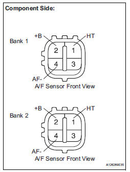
(a) Disconnect the A5 or A6 A/F sensor connector.
(b) Measure the resistance according to the value(s) in the table below.
Standard resistance: 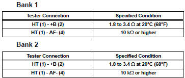
(c) Reconnect the A/F sensor connector.
Result 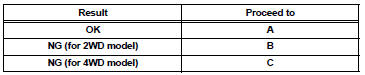

3 CHECK HARNESS AND CONNECTOR (A/F SENSOR - ECM)
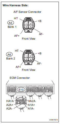
(a) Disconnect the A5 or A6 A/F sensor connector.
(b) Turn the ignition switch to the ON position.
(c) Measure the voltage according to the value(s) in the table below.
Standard voltage 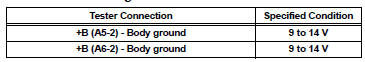
(d) Turn the ignition switch off.
(e) Disconnect the E10 ECM connector.
(f) Measure the resistance according to the value(s) in the table below.
Standard resistance: 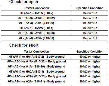
(g) Reconnect the ECM connector.
(h) Reconnect the A/F sensor connector.

4 PERFORM CONFIRMATION DRIVING PATTERN

5 CHECK WHETHER DTC OUTPUT RECURS (DTC P2A00 AND/OR P2A03)
(a) Read the DTCs using the intelligent tester.
(b) Select the following menu items: DIAGNOSIS / ENHANCED OBD II / DTC INFO / PENDING CODES.
Result 

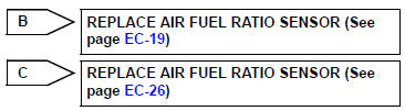
6 REPLACE AIR FUEL RATIO SENSOR
(a) Replace the air fuel ratio sensor (for 2WD model (See page EC-19) or 4WD model (See page EC-26)).

7 PERFORM CONFIRMATION DRIVING PATTERN

8 CHECK WHETHER DTC OUTPUT RECURS (DTC P2A00 AND/OR P2A03)
(a) Read the DTCs using the intelligent tester.
(b) Select the following menu items: DIAGNOSIS / ENHANCED OBD II / DTC INFO / PENDING CODES.
Result

END
 ECM / PCM Internal Engine Off Timer Performance
DTC SUMMARY
DESCRIPTION
To ensure the accuracy of the EVAP (Evaporative Emission) monitor values, the
soak timer, which is built
into the ECM, measures 5 hours (+/- 15 minutes) from when the ...
 Active Control Engine Mount System
DESCRIPTION
LOCATION
The Active Control Engine Mount (ACM) system decreases engine vibration at
engine idling using the
ACM VSV. The VSV is controlled by a pulse signal transmitted to the VSV f ...
Other materials:
Rear Blower Motor Circuit
DESCRIPTION
Power to the rear blower motor is supplied from the battery via the RR A/C
relay.
The rear blower motor speed level varies between 0 and 31 based on the voltage
difference measured
between the terminals of the motor.
The voltage difference measured between the terminals of th ...
Checking the messages
Display the message inbox screen.
Select the desired message from the list.
Check that the message is displayed.
E-mails: Select “Mark
Unread” or “Mark Read” to
mark mail unread or read on
the message inbox screen.
This function is available when “Update Read Stat ...
Reassembly
1. INSTALL CENTER CLUSTER MODULE KNOB NO.6
(for Automatic Air Conditioning System)
2. INSTALL CENTER CLUSTER MODULE KNOB NO.5
(for Automatic Air Conditioning System)
3. INSTALL CLOCK ORNAMENT
4. INSTALL PRINTED WIRE INTEGRATION BOARD
SUB-ASSEMBLY (for Automatic Air Conditioning
System)
5. IN ...
