Toyota Sienna Service Manual: Front Airbag Sensor RH Circuit Malfunction
DTC B1148/36 Front Airbag Sensor RH Circuit Malfunction
DESCRIPTION
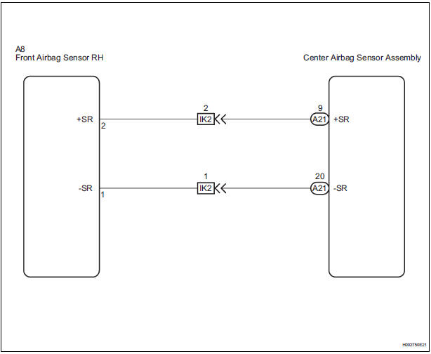
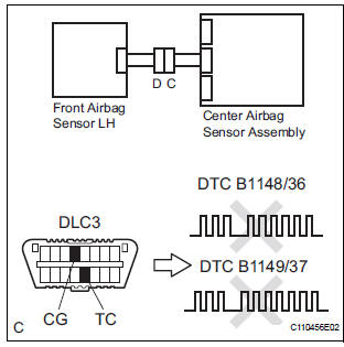
The front airbag sensor RH circuit consists of the center airbag sensor assembly and front airbag sensor RH. If the center airbag sensor assembly receives signals from the front airbag sensor RH, it judges whether or not the SRS should be activated.
DTC B1148/36 is recorded when a malfunction is detected in the front airbag sensor RH circuit.
|
DTC No. |
DTC Detecting Condition |
Trouble Area |
|
B1148/36 |
|
|
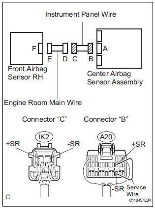
WIRING DIAGRAM
INSPECTION PROCEDURE
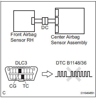
1 CHECK DTC
- Turn the ignition switch to the ON position, and wait for at least 60 seconds.
- Clear the DTCs stored in memory (5).
- Turn the ignition switch to the LOCK position.
- Turn the ignition switch to the ON position, and wait for at least 60 seconds.
- Check the DTCs (5).
OK: DTC B1148/36 is not output.
HINT: Codes other than DTC B1148/36 may be output at this time, but they are not related to this check.
 Go to step 2

USE SIMULATION METHOD TO CHECK
2 CHECK CONNECTION OF CONNECTORS
- Turn the ignition switch to the LOCK position.
- Disconnect the negative (-) terminal cable from the battery, and wait for at least 90 seconds.
- Check that the connectors are properly connected to the center airbag sensor assembly and the front airbag sensor RH.
OK: The connectors are connected.
 CONNECT CONNECTORS

3 CHECK FRONT AIRBAG SENSOR RH CIRCUIT (OPEN)
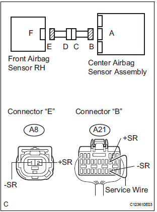
- Disconnect the connectors from the center airbag sensor assembly and the front airbag sensor RH.
- Using a service wire, connect A21-9 (+SR) and A21-20 (-
SR) of connector "B".
NOTICE: Do not forcibly insert a service wire into the terminals of the connector when connecting.
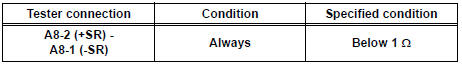
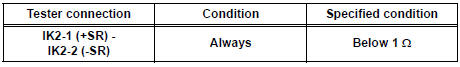
- Measure the resistance according to the value(s) in the table below.
Standard resistance
 Go to step 5

4 CHECK FRONT AIRBAG SENSOR RH
- Disconnect the service wire from connector "B".
- Connect the connector to the center airbag sensor assembly.
- Interchange the front airbag sensor RH with LH, and connect the connectors to them.
- Connect the negative (-) terminal cable to the battery, and wait for at least 2 seconds.
- Turn the ignition switch to the ON position, and wait for at least 60 seconds.
- Clear the DTCs stored in memory (5).
- Turn the ignition switch to the LOCK position.
- Turn the ignition switch to the ON position, and wait for at least 60 seconds.
- Check the DTCs (5).
Result
HINT: Codes other than DTC B1148/36 and B1149/37 may be output at this time, but they are not related to this check.
 REPLACE CENTER AIRBAG SENSOR
ASSEMBLY
REPLACE CENTER AIRBAG SENSOR
ASSEMBLY
 REPLACE FRONT AIRBAG SENSOR
RH
REPLACE FRONT AIRBAG SENSOR
RH

USE SIMULATION METHOD TO CHECK
5 CHECK INSTRUMENT PANEL WIRE (OPEN)
- Disconnect the instrument panel wire connector from the
engine room main wire.
HINT: The service wire has already been inserted into connector "B".
- Measure the resistance according to the value(s) in the table below.
Standard resistance
 REPAIR OR REPLACE INSTRUMENT
PANEL
WIRE
REPAIR OR REPLACE INSTRUMENT
PANEL
WIRE

REPAIR OR REPLACE ENGINE ROOM MAIN WIRE
 Side Airbag Sensor Assembly LH Circuit Malfunction
DTC B1141/33 Side Airbag Sensor Assembly LH Circuit Malfunction
DESCRIPTION
The side airbag sensor LH circuit consists of the center airbag sensor
assembly and side airbag sensor
LH.
If the ce ...
 Front Airbag Sensor LH Circuit Malfunction
DTC B1149/37 Front Airbag Sensor LH Circuit Malfunction
DESCRIPTION
The front airbag sensor LH circuit consists of the center airbag sensor
assembly and front airbag sensor
LH.
If the center a ...
Other materials:
Removal
1. REMOVE ROOF HEADLINING ASSEMBLY
2. REMOVE SLIDING ROOF SIDE GARNISH LH
Disengage the 3 claws.
Disengage the rear clip.
Disengage the front clip.
Remove the slide garnish by pulling it rearward.
3. REMOVE SLIDING ROOF SIDE GARNISH RH
HINT:
Use the same procedures described abov ...
Installation
1. INSTALL SEAT MEMORY SWITCH
2. INSTALL FRONT DOOR TRIM BOARD SUBASSEMBLY
LH
3. INSTALL POWER WINDOW REGULATOR MASTER
SWITCH ASSEMBLY
4. INSTALL FRONT DOOR INSIDE HANDLE BEZEL
PLUG LH
5. INSTALL FRONT DOOR LOWER FRAME BRACKET GARNISH LH
Engage the 4 claws to install the seat me ...
Fog light switch
The fog lights secure excellent visibility in difficult driving
conditions,
such as in rain and fog.
The illustration is intended as an example.
Turns the fog lights on
*1 or
*2
Turns the fog lights off
*1: For U.S.A.
*2: For Canada
Fog lights can be used when
The headlights ...
